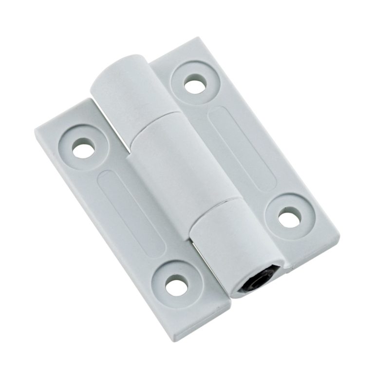
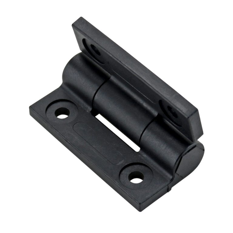
PA6 is wear-resistant and lightweight, while zinc alloy is sturdy and durable. It is suitable for industrial control cabinets, instruments, and medical equipment housings, ensuring that the cover can stay at any angle, improving operational safety and convenience.
Product Features
Key Features
Details
Adjustable Torque Design
Torque resistance can be easily adjusted using a Phillips screwdriver, enabling precise positioning and stable holding at any angle.
Multiple Torque Ranges
Various torque options (0.1 N·m – 0.5 N·m) are available across models to meet different application requirements.
Material Versatility
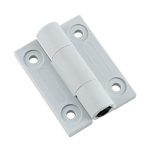
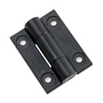
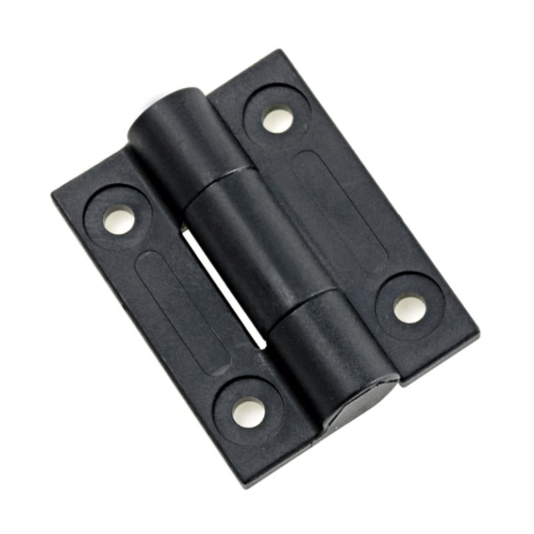
Offered in PA6 (lightweight and wear-resistant) and zinc alloy (sturdy and durable), catering to both lightweight and heavy-duty usage needs.
Various Surface Finishes
Surface treatments include Black, White, Black Electrophoresis Coating, and Sandblasted Nickel Plating, ensuring both aesthetics and corrosion resistance.
Wide Application Compatibility
Ideal for industrial control cabinets, instrumentation panels, and medical equipment housings where panel positioning and ease of operation are essential.
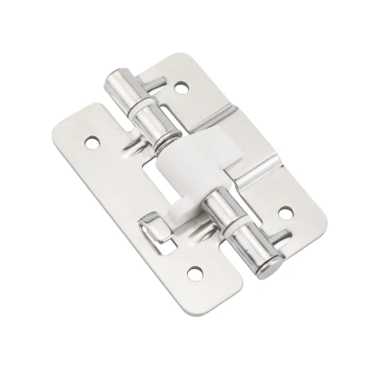
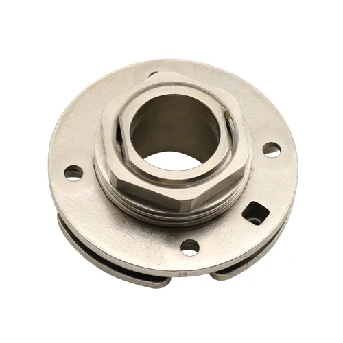
Secure Locking Mechanism
Equipped with a locking nut to secure torque settings after adjustment, enhancing operational safety and stability.
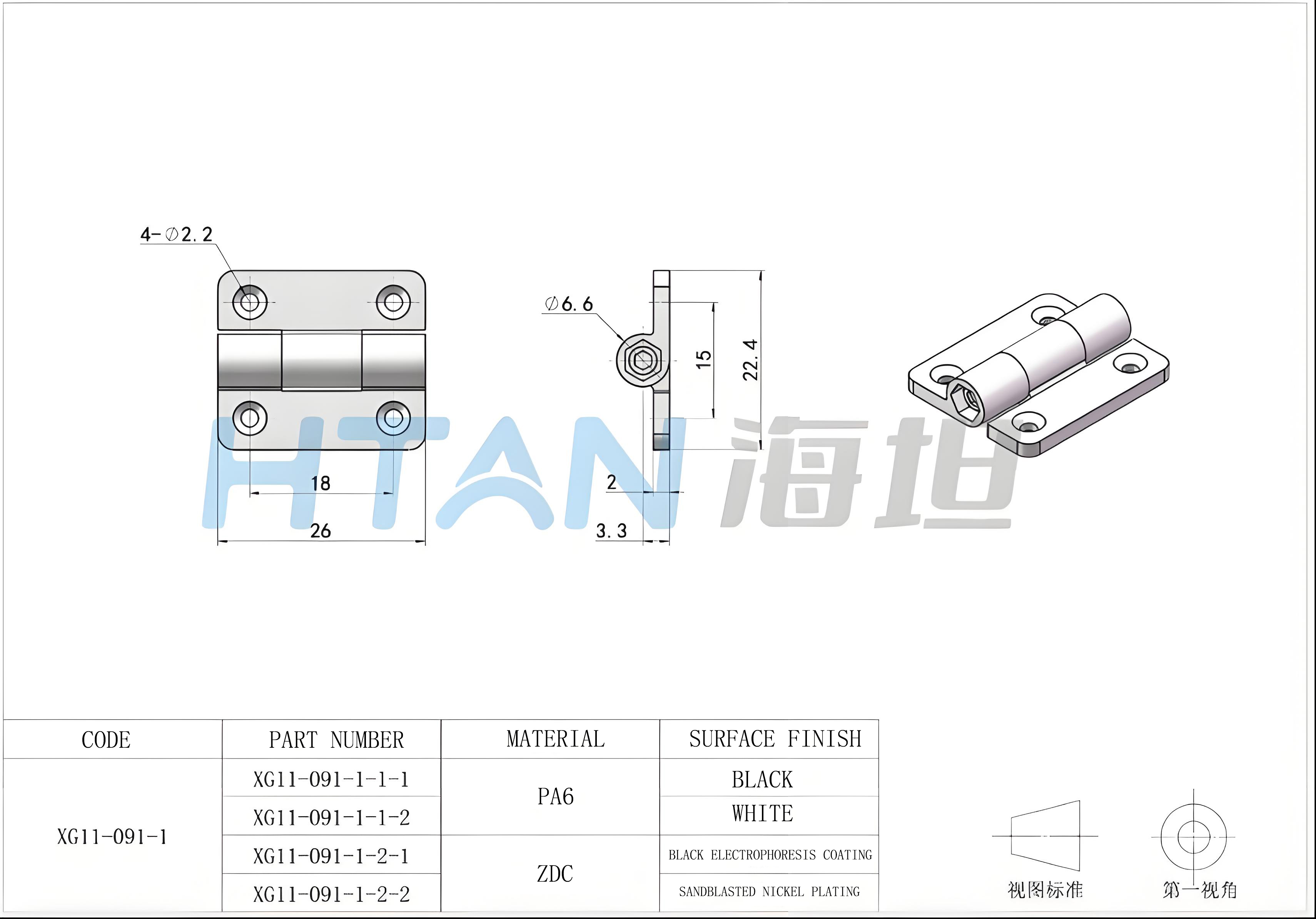
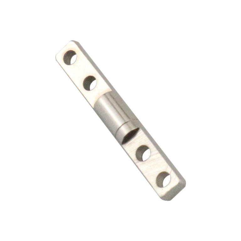
Model: XG11-091-1
Model
Material
Surface Finish
Torque Range
XG11-091-1-1-1
PA6
Black
0.1 N·m – 1.0 N·m
XG11-091-1-1-2
PA6
White
0.1 N·m – 1.0 N·m
XG11-091-1-2-1
ZDC
Black Electrophoresis Coating
0.1 N·m – 1.0 N·m
XG11-091-1-2-2
ZDC
Sandblasted Nickel Plating
0.1 N·m – 1.0 N·m
Torque Adjustment Guide
Use a Phillips screwdriver to loosen the adjustment screw.
Rotate the hinge to the desired position and test the torque resistance.
If greater torque is required, turn the adjustment screw clockwise in small increments.
If less torque is required, turn the adjustment screw counterclockwise.
Test the torque after each adjustment until the desired resistance is achieved.
Once satisfied, tighten the lock nut to secure the adjustment.