How to Calculate Torque Hinge Requirements: Industry Case Studies
Selecting a 토크 힌지 by catalog rating alone is one of the most common — and costly — engineering mistakes in industrial design. A hinge that passes static load calculations on paper can fail within months when dynamic forces, temperature variation, and real-world installation tolerances are not factored in.
This guide is built around three complete, worked calculation examples drawn from real-world applications: a consumer laptop display, a medical imaging arm, and a heavy industrial enclosure door. Each example walks through the full calculation sequence — from measuring the panel to specifying the final hinge — and highlights the mistakes that cause field failures in each sector.
If you need a foundation in torque hinge principles before running these calculations, the Torque Hinge Selection Guide covers the underlying mechanics, static vs. dynamic torque, and the complete selection workflow. This article picks up where that guide leaves off — at the point where theory meets real application data.
The Calculation Formula: Quick Reference
All three case studies use the same base formula. This section is a quick reference only — for a full explanation of each variable, see the 토크 계산 공식 section in the selection guide.
Treq = W × L × sin(θ)
Tdesign = Treq × SF
- W = Panel weight in Newtons (N) — convert kg × 9.81
- L = Moment arm: perpendicular distance from hinge axis to panel center of gravity (m)
- θ = Angle at worst-case position (peak torque almost always occurs at 90° horizontal, where sin θ = 1)
- SF = Safety factor: 1.2–1.5 for stable indoor use; 1.5–2.0 for vibration, outdoor, or high-cycle environments
Unit note: The formula above uses SI units (N, m, N·m). If working in imperial units: Torque (lb·in) = Weight (lbs) × Distance (inches) × SF. To convert: 1 N·m ≈ 8.85 lbf·in.
Case Study 1: Consumer Laptop Display
Peak torque always occurs at θ = 90° (panel horizontal) — always calculate for this worst case
Application Context
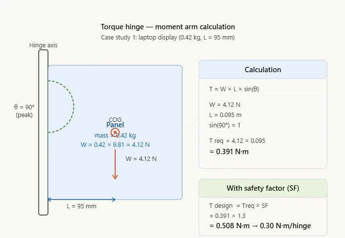
A 14-inch consumer laptop with a total display assembly mass of 0.42 kg. The hinge pivot is at the bottom edge of the display; the panel’s center of gravity is at geometric center — approximately 95 mm from the pivot axis. Two hinges share the load symmetrically. Target product life: 20,000 open/close cycles.
Step-by-Step Calculation
- Convert mass to weight: W = 0.42 kg × 9.81 = 4.12 N
- Moment arm: L = 0.095 m (distance from pivot to COG at geometric center)
- Peak torque (at 90° horizontal): Treq = 4.12 N × 0.095 m = 0.391 N·m
- Apply safety factor (SF = 1.3 for controlled, low-vibration environment): Tdesign = 0.391 × 1.3 = 0.508 N·m
- Per-hinge torque (2 hinges, load sharing assumed equal with 20% margin): 0.508 ÷ 2 × 1.2 = ≈ 0.30 N·m per hinge
Specification and Lessons
Final specification: Bidirectional torque hinge, 0.30–0.35 N·m per hinge, non-indexed (infinite free-stop), cycle life ≥ 20,000, torque variation ≤ ±10% over rated life.
Most common mistake in this sector: Specifying torque based on mass (kg) rather than weight (N). A hinge specified at “0.04 kg·m” instead of “0.39 N·m” will be undersized by a factor of approximately 9.81 — causing the display to drift or drop immediately after installation.
Validation requirement: Prototype testing must confirm torque consistency within ±10% across the full rotation range. Torque decay after the rated cycle life should not exceed 15% of initial value. For mass-market consumer electronics, 100% in-line torque profiling during production is standard practice.
Case Study 2: Medical Imaging Equipment Display Arm
Application Context
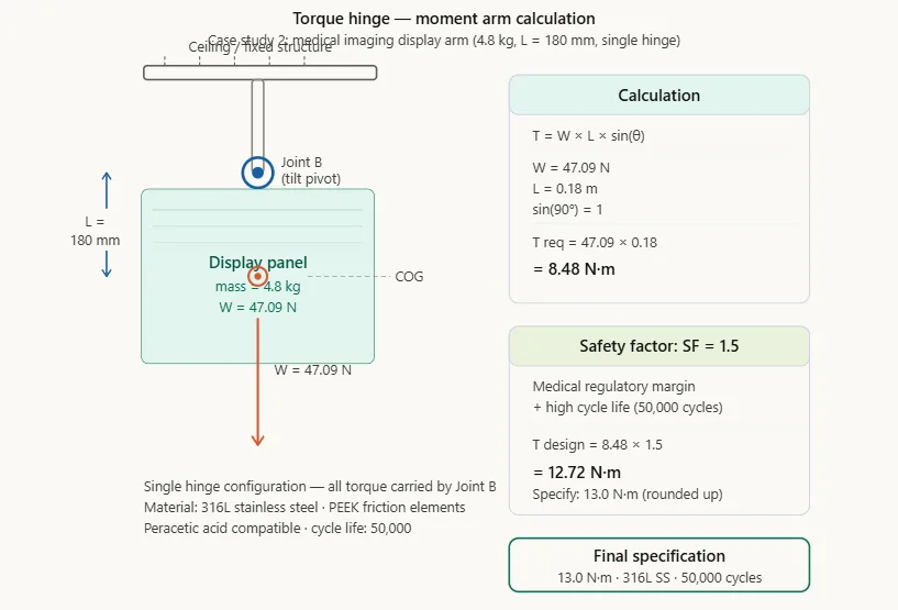
A ceiling-mounted medical display arm for a radiology workstation. The arm carries a 24-inch monitor with total moving assembly mass of 4.8 kg. The joint being specified (Joint B — the display tilt joint) carries the display mass only; the COG is 180 mm from the tilt pivot. Operating environment: hospital radiology suite, regular chemical disinfection with peracetic acid-compatible cleaners. Required cycle life: 50,000 cycles (10 adjustments/day × 5 days × 50 weeks × 20 years).
Step-by-Step Calculation
- Convert mass to weight: W = 4.8 kg × 9.81 = 47.09 N
- Moment arm: L = 0.18m
- Peak torque: Treq = 47.09 N × 0.18 m = 8.48 N·m
- Apply safety factor (SF = 1.5 — medical equipment, high cycle life, regulatory margin required): Tdesign = 8.48 × 1.5 = 12.72 N·m
- Single-hinge configuration: Specify at 12.72 N·m minimum, rounded up to 13.0 N·m for catalog selection.
Specification and Lessons
Final specification: Bidirectional torque hinge, 13.0 N·m, 316L stainless steel body and shaft, PEEK or PTFE friction elements (compatible with peracetic acid disinfection), cycle life ≥ 50,000, torque variation ≤ ±10% after 50,000 cycles.
Most common mistake in this sector: Selecting standard industrial hinges without verifying chemical compatibility. Peracetic acid and many hospital-grade disinfectants degrade standard polymer friction elements within months, causing rapid torque loss. Always request a chemical compatibility data sheet from the hinge manufacturer before specifying for medical environments.
Regulatory note: Medical device components used in Class II or Class III devices typically require material traceability records and test reports validating torque performance after simulated sterilization exposure. Budget for this documentation during the supplier qualification process. For further detail on medical-specific hinge requirements, see our guide on 의료 기기용 토크 힌지 선택.
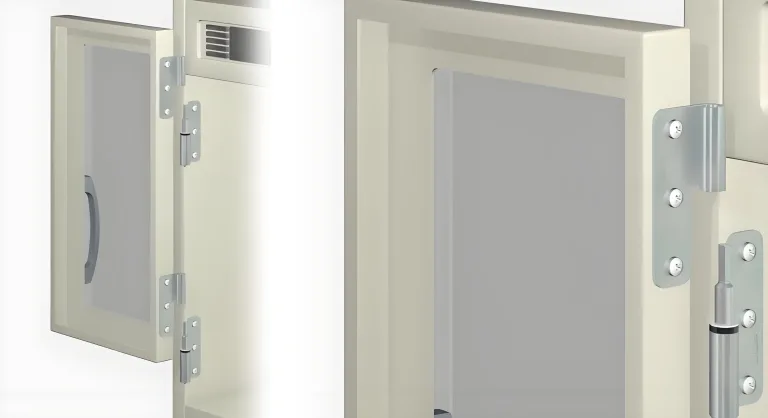
Case Study 3: Heavy Industrial Enclosure Door
Application Context
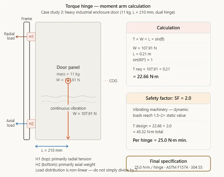
A steel access door on a CNC machining center enclosure. Door mass: 11 kg (including integrated safety interlock hardware). Door width: 420 mm; COG at geometric center, 210 mm from hinge axis. The machine operates in a production environment with continuous vibration from the spindle and coolant pump. Two hinges, top and bottom. Required cycle life: 30,000 cycles (approximately 12 openings/day × 250 days/year × 10 years).
Step-by-Step Calculation
- Convert mass to weight: W = 11 kg × 9.81 = 107.91 N
- Moment arm: L = 0.21 m
- Peak torque: Treq = 107.91 N × 0.21 m = 22.66 N·m
- Apply safety factor (SF = 2.0 — continuous vibration environment, production-critical downtime risk): Tdesign = 22.66 × 2.0 = 45.32 N·m total
- Per-hinge torque (2 hinges, unequal loading — top hinge carries more radial load, bottom more axial): 사용 25 N·m per hinge as the minimum rated specification. Do not simply divide by 2 without verifying the load distribution in CAD.
Specification and Lessons
Final specification: Heavy-duty torque hinge, 25 N·m minimum per hinge, 304 stainless steel (coolant splash resistance), weld-on or M6 bolt-on mounting, cycle life ≥ 30,000 per ASTM F1574.
Most common mistake in this sector: Using SF = 1.3 (sufficient for static conditions) in a vibrating environment. In vibrating machinery, the effective dynamic load on the hinge can be 1.5–2× the static value depending on the vibration frequency and amplitude. The additional SF = 2.0 here is not conservative overengineering — it reflects the real dynamic loading pattern from the spindle and pump vibration.
Maintenance note: In high-cycle industrial applications, implement a quarterly torque measurement schedule using a calibrated torque gauge. Replace hinges when measured torque drops below 80% of the original specification — do not wait for visible failure. Unplanned downtime on a CNC machining center typically costs far more than a scheduled hinge replacement.
Cross-Sector Comparison: What the Numbers Reveal
Placing the three case studies side by side surfaces patterns that are not obvious from single-application experience:
| 매개변수 | 노트북 디스플레이 | Medical Arm | Industrial Door |
|---|---|---|---|
| Panel mass | 0.42 kg | 4.8 kg | 11 kg |
| Moment arm | 95 mm | 180 mm | 210 mm |
| Treq (peak) | 0.39 N·m | 8.48 N·m | 22.66 N·m |
| Safety factor applied | 1.3× | 1.5× | 2.0× |
| Tdesign | 0.51 N·m total | 12.72 N·m | 45.32 N·m total |
| Per-hinge specification | 0.30 N·m | 13.0 N·m | 25.0 N·m |
| Required cycle life | 20,000 | 50,000 | 30,000 |
| Critical failure mode | Torque drift (display droops) | Chemical degradation | Vibration fatigue |
The torque range across these three sectors spans roughly 80:1 (0.30 N·m to 25.0 N·m), yet the underlying calculation methodology is identical. What changes sector to sector is the safety factor, the dominant failure mode, and the material/documentation requirements — not the physics.
Common Calculation Errors and How to Prevent Them
The following errors account for the majority of field failures and warranty returns across all three sectors examined above.
| Error | Typical Consequence | Prevention | Real Example |
|---|---|---|---|
| Using mass (kg) instead of weight (N) | Hinge undersized by factor of 9.81 | Always multiply kg × 9.81 before calculating torque | Display hinges specified at 0.04 “kg·m” instead of 0.39 N·m — failed in first week |
| Using geometric center as COG for asymmetric panels | Actual peak torque 20–50% higher than calculated | Use CAD analysis or physical balance test for non-uniform panels | Server rack door with mounted PDU — COG shifted 80 mm from geometric center |
| SF = 1.0 (no safety factor) | Failure under first abnormal load condition | Minimum SF = 1.2 for all applications; 1.5–2.0 for vibration/outdoor | Industrial oven door — failed during first deep cleaning because wet gasket added 15% mass |
| No temperature testing | 15–30% torque loss at high temp; 20–40% gain at low temp | Test prototypes at min and max operating temperature before production release | Outdoor telecom enclosure — door would not stay open in summer at 45°C |
| Ignoring dynamic loads in vibrating environments | Premature fatigue failure despite passing static calculations | Add 25–50% to Treq for machinery vibration; use SF = 2.0 minimum | Server rack hinge passed static load but failed seismic qualification testing |
Testing and Validation Standards by Sector
Specifying the correct torque value is necessary but not sufficient. The hinge must also be validated against the cycle life and environmental conditions of the application. The following standards are referenced in procurement specifications and regulatory submissions across the three sectors covered in this article:
| 표준 | Minimum Cycles | Temperature Testing | Typical Sectors |
|---|---|---|---|
| ASTM F1574 | 10,000 | Optional | General industrial, enclosures |
| MIL-HDBK-5 | 25,000 | −54°C to +71°C required | Aerospace and defense |
| IEC 60068-2-14 | - | Thermal shock −40°C to +85°C | Industrial electronics, outdoor |
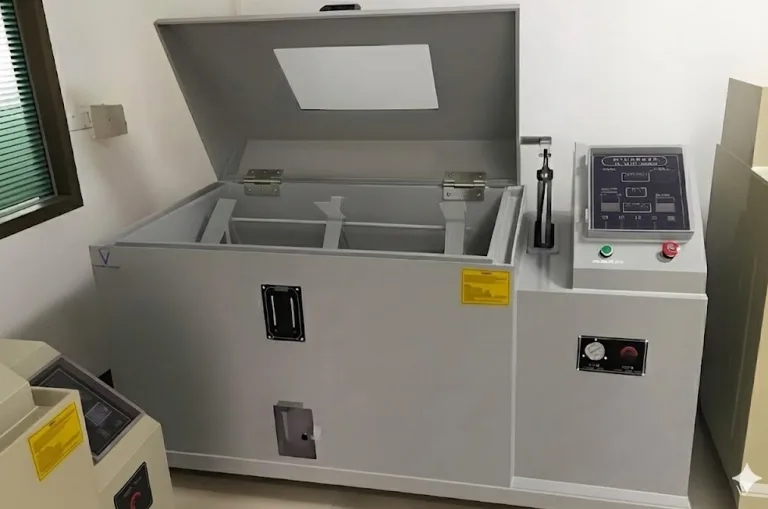
| ISO 9227 | - | Salt spray 500+ hours | Marine, coastal, outdoor |
For critical applications, document torque decay curves at regular intervals throughout the test cycle — typically every 5,000 cycles. These curves quantify performance degradation with wear and establish evidence-based replacement intervals. Hinges showing 15% or greater torque reduction from baseline should be flagged for replacement in preventive maintenance schedules.
Advanced Applications: Smart Hinges and Custom Engineering
Smart Hinge Integration
Emerging hinge designs incorporate embedded sensors capable of reporting real-time position, cumulative cycle count, and live torque data to building management or equipment monitoring systems. In production environments where unplanned downtime carries high costs — CNC machining, semiconductor fabrication, pharmaceutical filling lines — predictive maintenance based on torque decay trends can eliminate reactive failure entirely.
Current development work includes microcontroller-driven adaptive torque mechanisms that adjust friction element preload as internal components wear, maintaining consistent operating feel throughout the rated service life. These systems are particularly relevant for robotics and automated equipment where consistent actuator behavior is critical to positional accuracy.
When Standard Catalog Hinges Cannot Meet Requirements
Custom hinge engineering is justified when standard products cannot meet application requirements. Representative examples include extreme-temperature environments (below −100°C for cryogenic instrument applications), near-vacuum operating conditions for space instrumentation, integrated position feedback for closed-loop control systems, and non-standard load geometries that fall outside the rated capacity of available catalog products.
Custom hinge development typically requires 12–16 weeks from specification to first article delivery. Costs run three to five times higher than equivalent catalog products. Prototype validation before committing to production tooling is essential — custom tooling changes after production release are expensive and time-consuming. For custom torque hinge inquiries, see our custom torque hinge development process.
자주 묻는 질문
Q1: I have a 20-lb electronic enclosure door with its COG 6 inches from the hinge axis. What torque hinge do I need?
Treq = 20 lbs × 6 in = 120 lb·in. Apply SF = 1.5: Tdesign = 180 lb·in (≈ 20.3 N·m). If using two hinges, specify each at minimum 108 lb·in (12.2 N·m), adding 20% for unequal load sharing. Always verify with prototype testing — particularly if the door carries mounted components that shift the COG from the assumed position.
Q2: Can I use the same torque hinge calculation method for a horizontal panel (like a machine tool access hatch)?
Yes, with one important difference. For a panel rotating in the horizontal plane (opening like a trapdoor), the gravitational moment varies with the opening angle — peak torque occurs when the panel is fully horizontal (90° from vertical). Use sin(θ) to calculate torque at each position if the panel stops at an angle other than 90°. The formula remains T = W × L × sin(θ), where θ is measured from the vertical (fully closed) position.
Q3: My hinge passes the static torque calculation but the door droops after a few months. What went wrong?
The most likely causes are: (1) torque decay from lubricant degradation — specify PTFE-impregnated friction elements or synthetic ester-based lubricants for longer service; (2) the safety factor was insufficient — if the installed environment has vibration or temperature variation not accounted for in the original calculation, the hinge is effectively operating above its rated load; (3) manufacturing tolerance variation — real hinges have torque tolerances of ±10–15%, so a hinge specified at exactly the calculated minimum may be below the threshold in service. Always specify with at least 20% margin above Tdesign.
Q4: How do I validate that the hinge I have selected will meet the required cycle life?
Request a torque decay curve from the manufacturer — this documents how torque output changes from cycle 0 through the rated cycle life under specified load and temperature conditions. If no data exists, budget for prototype testing per ASTM F1574 or the relevant sector standard before committing to production. For critical applications, define the replacement threshold in your maintenance procedure: typically 15% torque reduction from the initial measured value.
Q5: What is the correct safety factor for outdoor security camera mounts?
Use SF = 2.0 minimum. Calculate the combined load of camera weight plus maximum wind force at the rated wind speed for the installation location — wind loading can add the equivalent of 30–50 lbs of effective force in storm conditions. Specify 316 stainless steel with minimum IP67 environmental rating. Avoid carbon steel or zinc alloy hardware in outdoor environments — untreated zinc alloy typically shows significant corrosion within 6–12 months in coastal or industrial-atmosphere conditions. For related material and environmental selection guidance, see 해안 프로젝트용 NEMA 4X 힌지.
Q6: How much do custom torque hinges cost compared to standard products?
Custom hinges typically cost three to five times more than catalog equivalents and carry lead times of 12–16 weeks for first articles. Custom development is justified when standard products cannot meet specific requirements such as extreme temperatures, unusual load geometries, integrated sensors, or non-standard materials. Always request and test prototypes before releasing production tooling — custom tooling changes after production release are both expensive and time-consuming.