Charnières à couple réglable : Principes, structure et applications
En ingénierie, comment faire pour qu'un couvercle ou un présentoir lourd reste en place quel que soit l'angle (contrôle de la position), sans "s'affaisser lentement" au fil du temps ?
Les solutions traditionnelles à base de ressorts à gaz sont complexes et sujettes à des défaillances. La véritable solution est la charnière à couple réglable, un composant qui offre une résistance de maintien constante en utilisant uniquement une "friction contrôlée" interne pour un positionnement précis.
Mais comment les ingénieurs peuvent-ils éviter l'erreur de conception la plus fréquente : une mauvaise estimation du couple ?
Ce guide définitif fournit la réponse ultime, depuis les normes fondamentales de physique et de fiabilité (comme le test de 25 000 cycles) jusqu'aux calculs précis.
Qu'est-ce qu'une charnière à couple réglable ?
Définition précise de la charnière à couple réglable
Définition de base :
Une charnière à couple réglable est un type particulier de charnière mécanique. Sa fonction principale est de fournir une résistance constante et prévisible sur toute la plage de mouvement de rotation de la charnière grâce à un mécanisme interne intégré de "frottement contrôlé".
Cette résistance est appelée couple.
Caractéristiques principales :
Cette résistance constante permet à la charnière d'assurer une fonction de "contrôle de position".
Grâce à cette fonction, les utilisateurs peuvent déplacer en douceur des portes, des couvercles, des présentoirs ou des bras dans l'angle de leur choix et, une fois relâché, l'objet reste automatiquement dans cette position, sans nécessiter de dispositifs de verrouillage, de ressorts à gaz ou de tiges de support supplémentaires.
Le sens du mot "ajustable" :
Contrairement à charnières à couple fixeLa caractéristique "réglable" signifie que les utilisateurs - généralement des ingénieurs ou des techniciens sur site - peuvent régler ou modifier avec précision le couple de frottement en cours d'utilisation grâce à un mécanisme de réglage externe sur la charnière (tel qu'une vis de réglage).
Cela permet à la charnière de s'adapter à différents poids de charge ou de compenser la dégradation des performances après une utilisation à long terme.
La valeur du "contrôle de la position"
La fonction de "contrôle de position" est la valeur commerciale et technique la plus importante des charnières à couple réglable.
Simplifier la conception et réduire les coûts :
Il élimine le besoin de composants auxiliaires tels que les ressorts à gaz, les goupilles de verrouillage mécaniques, les loquets magnétiques ou les limiteurs.
Réduire les points de défaillance :
Cette conception simplifiée permet non seulement de réduire le coût de la nomenclature du produit, mais aussi de minimiser de manière significative les risques potentiels d'incendie. points de défaillance.
Améliorer l'expérience de l'utilisateur :
Il offre aux utilisateurs finaux une expérience tactile haut de gamme, fluide et silencieuse.
Lors du déplacement de lourdes couvertures ou du réglage de moniteurs médicaux, cette sensation d'amortissement contrôlé et souple est un indicateur clé de la qualité du produit.
Distinction fondamentale : Charnière de couple vs. charnière d'amortissement vs. charnière à ressort
Dans les applications industrielles, ces trois types de charnières fonctionnelles sont souvent les suivants confus. Bien que charnières d'amortissement et les charnières à ressort génèrent également un couple au sens large, leur les mécanismes physiques et objectifs de la demande sont totalement différents.
Charnière à couple réglable (friction) :
Sa résistance est due à frottement statique force, ce qui signifie que son couple de sortie est indépendant de la vitesse angulaire.
Que l'utilisateur déplace le panneau rapidement ou lentement, la résistance (couple) reste constante.
Il s'agit de la base physique pour atteindre "contrôle de position".
Charnière amortissante :
Sa résistance provient de la cisaillement des fluides visqueux (comme l'huile de silicone), de sorte que son couple de sortie est fortement liée à la vitesse angulaire.
Plus le mouvement est rapide, plus la résistance est grande.
Sa fonction principale est "mise en mémoire tampon" ou "soft-close" (fermeture en douceur)comme dans les portes d'armoires, et il ne peut s'arrêter à aucune position intermédiaire.
Charnière à ressort :
Ce type d'appareil stocke et libère énergie potentielle (par exemple, les ressorts de torsion).
Sa fonction première est de "auto-fermeture" ou "auto-ouvert" (comme dans les portes coupe-feu ou les boîtes à bijoux).
C'est le cas pas fournissent une résistance constante.
Tableau comparatif des performances des charnières fonctionnelles clés
| Caractéristique | Charnière à couple réglable | Charnière d'amortissement | Charnière à ressort |
|---|---|---|---|
| Principe de base | Friction statique contrôlée (Friction) | Cisaillement des fluides visqueux (Viscosité) | Énergie potentielle élastique (ressort) |
| Caractéristique de résistance | Couple constant (indépendant de la vitesse) | Couple lié à la vitesse | Couple angulaire |
| Fonction principale | Contrôle de position | Soft-Close / Buffering | Auto-fermeture/ouverture |
| Ajustement | Réglable | Généralement non réglable | Généralement non réglable |
| Application typique | Moniteurs médicaux, protections industrielles, machines POS | Portes d'armoires haut de gamme, sièges de toilettes | Portes coupe-feu, couvercles de boîtes à fermeture automatique |
Analyse approfondie du principe de fonctionnement - Physique de la "friction contrôlée
Modèle physique de base : Source de couple
Tout le secret des charnières à couple réglable réside dans le contrôle précis de la force de frottement statique.Principe de base : Le couple de rotation (τ) de la charnière provient de la force de frottement (Ff) générée entre les plaques de frottement internes.Formule physique : Force de frottement Ff = μ × N, où μ est le coefficient de frottement statique entre les matériaux des plaques de frottement, et N est la force normale appliquée aux plaques de frottement.Design Core : L'ensemble des objectifs de conception de la charnière sont au nombre de deux : maintenir la stabilité de la valeur μ sur une durée de vie extrêmement longue (par exemple, supérieure à 25 000 cycles) ; fournir aux utilisateurs un mécanisme fiable permettant d'ajuster précisément N.
Mécanisme clé : Ajustement de la "force normale"
Le "réglage" de la charnière est essentiellement l'ajustement de la "force normale N" : La charnière interne contient généralement un ou plusieurs ensembles de plaques de frottement (ou anneaux de frottement) qui se chevauchent : Lorsque l'utilisateur serre la "vis de réglage" externe, celle-ci pousse une plaque de pression ou un ensemble de plaques de frottement (ou d'anneaux de frottement) qui se chevauchent. Rondelles BellevilleTransmission de la force : Ces ressorts appliquent une pression axiale précise et soutenue (c'est-à-dire la "force normale N") à l'ensemble de la pile de plaques de frottement : Plus la vis de réglage est serrée, plus N augmente, ce qui entraîne une augmentation de la force de frottement Ff et, en fin de compte, une augmentation du couple de sortie de la charnière τ.L'utilisation de rondelles Belleville constitue l'ingéniosité de cette conception. Elles fournissent une courbe de pression relativement constante. Même si les plaques de frottement subissent une usure mineure entraînant une réduction de l'épaisseur après une utilisation à long terme (par exemple après 25 000 cycles), les ressorts peuvent automatiquement compenser ce changement, maintenant ainsi le couple dans la plage de ±20% de la spécification tout au long du cycle de vie.
Courbe caractéristique de couple constant
Si l'on trace le graphique de la relation entre le couple et l'angle de rotation d'une charnière à couple idéal, sa courbe devrait être une ligne droite. Cela signifie que, que le couvercle soit à 10°, 45° ou 90°, le couple de maintien fourni par la charnière est constant. Cela contraste fortement avec les courbes des charnières à ressort (le couple varie en fonction de l'angle) et des charnières à amortissement (le couple varie en fonction de la vitesse).
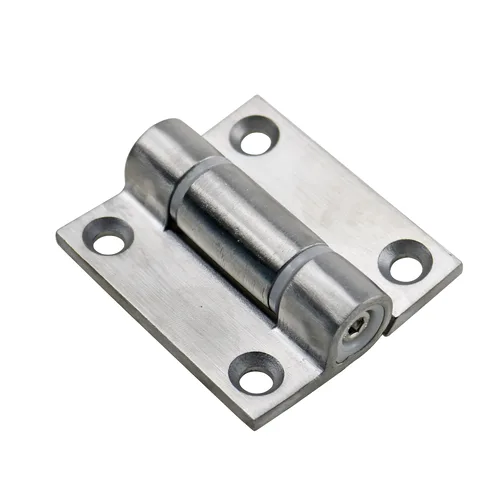
Désassemblage des structures internes et science des matériaux
Répondre d'abord : Quatre éléments essentiels
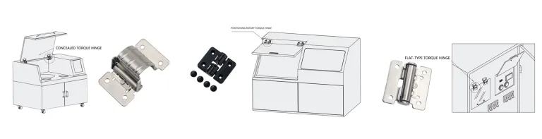
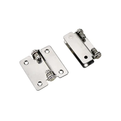
Les formes et les dimensions des charnières à couple réglable varient, mais leurs structures de base sont toutes composées des quatre types de composants clés suivants:Arbre/axe : arbre porteur central, transmet le couple. Il doit présenter une résistance élevée au cisaillement et un bon état de surface pour réduire l'usure dans les zones sans frottement.Disques de friction : Le cœur qui génère le couple. Il s'agit de la technologie de base de la charnière, qui apparaît généralement par paires (l'une fixée sur l'arbre, l'autre sur le boîtier).Mécanisme de réglage : Comme décrit ci-dessus, le système utilisé pour appliquer et modifier la "force normale N", qui consiste généralement en une vis de réglage et des rondelles Belleville (ou des pièces de ressort similaires).Boîtier : Il protège les composants internes de la pollution environnementale, telle que la poussière et l'humidité, et fournit des interfaces de montage normalisées (telles que des trous de vis) pour la fixation au produit.
Science des matériaux : Équilibre entre performance et coût
Le choix du matériau de la charnière détermine sa résistance, sa durée de vie, sa durabilité et son coût, et doit être rigoureusement choisi en fonction du scénario d'application final.
Comparaison des performances des matériaux de charnière courants et des scénarios d'application
| Type de matériau | Avantages principaux | Principaux inconvénients | Scénarios d'application typiques | Normes/performances associées |
|---|---|---|---|---|
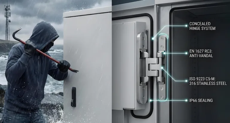
| Acier inoxydable (tel que SUS304) | Excellente résistance à la corrosion, résistance aux températures élevées, grande solidité, facile à nettoyer et à stériliser | Coût élevé, difficulté de traitement élevée | Équipement médical (nécessitant une stérilisation), machines pour l'industrie alimentaire, équipement pour l'extérieur ou l'environnement marin | Conforme au test de chaleur humide IEC 60068-2-78 ; compatible avec les salles blanches |
| Alliage de zinc (tel que Zamak) | Faible coût, facilité de moulage sous pression de formes complexes, bonne adhérence de l'électrodéposition et du revêtement | Solidité et résistance à la corrosion inférieures à celles de l'acier inoxydable, faible fluage à long terme | Périphériques électroniques grand public (machines POS), Mobilier de bureau, Portes d'armoires intérieures | Applications sensibles aux coûts, exigences modérées en matière de durée de vie (<20 000 cycles) |
| Plastiques techniques (tels que PEEK, PA) | Poids extrêmement léger, autolubrifiant (faible bruit), résistance aux produits chimiques, isolation électrique, non magnétique | Capacité de charge et rigidité moindres, sensibilité aux changements de température | Instruments de diagnostic médical légers, intérieurs d'avions (réduction du poids), couvertures d'équipements électroniques, équipements pour salles d'IRM | Tendances à la miniaturisation ; répondre aux besoins des environnements spéciaux (tels que les environnements non magnétiques) |

Normes faisant autorité et vérification des performances
Répondre d'abord : Normes de base pour l'évaluation des charnières de couple
La "fiabilité" d'une charnière dynamométrique ne dépend pas de son texte promotionnel, mais du fait qu'elle a passé avec succès des tests normalisés reconnus par l'industrie. Dans les applications critiques (médecine, aviation, industrie lourde), les charnières non certifiées présentent d'énormes risques pour la sécurité. Les ingénieurs professionnels doivent demander aux fournisseurs, lors de la sélection, des rapports d'essai pour les normes suivantes.
Test du cycle de vie
Données clés : Une référence de haute qualité reconnue dans l'industrie est une durée de vie de >25 000 cycles.Indicateur de dégradation des performances : Il ne suffit pas de réaliser 25 000 cycles. L'indicateur le plus critique est qu'à la fin du cycle de vie, le couple dynamique doit rester dans une fourchette de ±20% par rapport à la spécification du couple statique d'origine. Ce ±20% est un facteur clé qui doit être pris en compte lors de la conception. Cela signifie qu'une charnière ayant une force nominale de 10 N・m peut n'avoir qu'une force de maintien de 8 N・m à la fin de son cycle de vie. Ceci est directement lié au calcul de la "marge de sécurité" dans la cinquième partie - la conception doit compenser ce facteur.Numéros de normes de référence :ANSI/BHMA A156.17: L'American National Standards Institute (ANSI) a publié une norme sur la quincaillerie d'ameublement (y compris les charnières à fermeture automatique et à oscillation libre), dont la méthode d'essai cyclique a une valeur de référence importante.DIN EN 1935: Norme allemande/européenne sur la quincaillerie de bâtiment (charnières à un axe), bien que principalement pour les portes, les méthodes d'essai de cycle et d'essai de charge qu'elle définit sont celles de l'industrie.
Essais d'adaptabilité à l'environnement
Les performances des charnières peuvent varier de manière significative en fonction de la température et de l'humidité. Les normes de la série IEC 60068 sont la référence internationale pour l'évaluation de la fiabilité des composants électroniques et mécaniques dans différents environnements.IEC 60068-2-1) : Permet de s'assurer que la charnière ne tombe pas en panne ou ne se bloque pas en raison de la fragilité du matériau (en particulier les pièces en plastique) ou de changements radicaux dans les plaques de frottement (valeur μ) à basse température (par exemple -10°C).Essai à la chaleur sèche (CEI 60068-2-2) : Assure que les pièces en plastique technique ne se ramollissent pas à des températures élevées (telles que +50°C ou plus) et que le couple de frottement ne subit pas de "dégradation thermique" irréversible.Essai à la chaleur humide (IEC 60068-2-78) : Simule des environnements extrêmement humides (tels que 40°C, 90% d'humidité relative), en mettant l'accent sur la résistance à la rouille des charnières en acier inoxydable et sur la défaillance des matériaux de friction en raison de l'absorption et de la dilatation de l'humidité.
Référence rapide pour les numéros de normes techniques des charnières à clé
| Numéro standard | Nom de la norme (ou contenu clé) | Objectif du test |
|---|---|---|
| 3 (Données citées) | Essai du cycle de vie du fabricant | Vérifier si la dégradation du couple reste dans les limites de ±20% après >25 000 cycles. |
| IEC 60068-2-1 | Essais environnementaux Partie 2-1 : Essai A : Froid | Évaluer l'impact d'une basse température sur le coefficient de frottement (μ) et la fragilité du matériau. |
| IEC 60068-2-2 | Essais d'environnement - Partie 2-2 : Essai B : Chaleur sèche | Évaluer l'impact des températures élevées sur la dégradation des performances des matériaux de friction et sur le fluage. |
| IEC 60068-2-78 | Essais d'environnement - Partie 2-78 : Cabine d'essai : Chaleur humide en régime permanent | Évaluer la résistance à la corrosion et à l'expansion par absorption d'humidité du matériau. |
| ANSI/BHMA A156.17 | Charnières (à fermeture automatique et à pivotement libre) | Référence de l'industrie nord-américaine du meuble et de la quincaillerie en matière de durée de vie et de charge |
Guide de sélection et calcul précis du couple
Répondre d'abord : Raison principale de l'échec de la sélection
La raison la plus fréquente de l'échec de la sélection des charnières est l'erreur de calcul du couple. Cela se manifeste généralement par une sous-estimation de la demande de couple réelle, ce qui entraîne une incapacité à contrôler la position en position horizontale et un affaissement lent de la couverture : Sous-estimation de la demande réelle de couple : la charnière est incapable de "contrôler la position" en position horizontale et le couvercle s'affaisse lentement.Le CdG) : Division aveugle de la longueur de la couverture par 2, ce qui entraîne des écarts de calcul.
Formules faisant autorité pour le calcul du couple (évolution à trois niveaux)
De nombreuses sources fournissent formules de calcul du coupleavec une précision variable.
Premier niveau (formule d'estimation) :
Applicable aux cas où le matériau de couverture est uniforme et où le centre de gravité se trouve exactement au centre géométrique. Couple (T, unité N\cdotpm)=Poids du couvercle (W, unité kg)×9,8 (g)×Longueur du couvercle (L, unité m)2\text{Couple (T, unité N-m)} = \text{Poids du couvercle (W, unité kg)} \times 9.8 \, (\text{g}) \times \frac{\text{Longueur de la couverture (L, unité m)}}{2}Couple (T, unité N\cdotpm)=Poids de la couverture (W, unité kg)×9.8(g)×2Longueur de la couverture (L, unité m)
Cela correspond aux algorithmes "Hauteur de la porte × 1/2 × Poids de la porte" et "L / 2 × L × 9,8".
Deuxième niveau (Formule précise) (recommandé) :
Applicable lorsque le centre de gravité n'est pas au centre géométrique (comme les couvertures avec des écrans ou des poignées installés). Couple (T, unité N\cdotpm)=Poids du couvercle (W, unité kg)×9,8 (g)×Distance horizontale du centre de gravité au pivot (X1, unité m)\text{Couple (T, unité N-m)} = \text{Poids du couvercle (W, unité kg)} \times 9.8 \, (\text{g}) \time \text{Distance horizontale du centre de gravité au pivot (X1, unité m)}Couple (T, unité N\cdotpm)=Poids de la couverture (W, unité kg)×9.8(g)×Distance horizontale du centre de gravité au pivot (X1, unité m)
Cela correspond à l'algorithme "Distance horizontale X1 entre le centre de rotation et la position du centre de gravité × poids m".
Troisième niveau (formule dynamique) :
Applicable aux applications nécessitant l'analyse des variations de couple tout au long du processus de mouvement du couvercle. T(θ)=W×g×Lcog×cos(θ)T(\theta) = W \times g \times L_\text{cog} \times \cos(\theta)T(θ)=W×g×Lcog×cos(θ)
Où LcogL_\text{cog}Lcog est la distance en ligne droite entre le centre de gravité et le pivot, et θ\thetaθ est l'angle entre le couvercle et le plan horizontal.
Cette formule indique que lorsque le couvercle est en position horizontale (θ=0∘\theta = 0^\circθ=0∘), cos(0∘)=1\cos(0^\circ) = 1cos(0∘)=1, et le couple requis est maximal. Par conséquent, le choix de la charnière doit être basé sur ce couple maximal.
Exemple de calcul
Étant donné : Longueur de la couverture (L) = 0,5 m ; Poids de la couverture (W) = 3 kg. Supposons : Le couvercle est uniforme, le centre de gravité est au centre (L/2 = 0,25 m). Calculer le couple maximal T:T = W × g × (L / 2)T = 3 kg × 9,8 m/s² × 0,25 mT = 7,35 N-m
Considération clé : Pourquoi faut-il ajouter une marge de sécurité 30% ?
Après avoir calculé 7,35 N-m ci-dessus, il ne faut absolument pas choisir une charnière dont la limite supérieure de couple est de 8 N-m. Les meilleures pratiques de l'industrie recommandent d'ajouter au moins une marge de sécurité de 30%. Couple de sélection = 7,35 N-m × 1,3 = 9,55 N-m. Les ingénieurs doivent choisir une charnière dont la plage de réglage peut facilement couvrir 9,55 N-m (par exemple, un modèle de 5 à 12 N-m). Cette marge de sécurité 30% est utilisée pour compenser la dégradation de la durée de vie : Couvrir la dégradation des performances de ±20% mentionnée dans la norme.Erreur d'estimation du centre de gravité : Compenser l'incertitude de la mesure du centre de gravité.Charge dynamique : Compenser la charge supplémentaire due à la fermeture rapide du couvercle par l'utilisateur (force d'impact) ou au placement d'objets supplémentaires sur le couvercle (comme des tasses à café).
Analyse de cas du scénario de l'application interdomaine
Les charnières à couple réglable, grâce à leurs caractéristiques de "contrôle de position" et de "réglage", permettent de relever des défis techniques majeurs dans de nombreux domaines.
Application industrielle
Cas : Portes d'armoires de commande lourdes, protections de machines, panneaux d'inspection sur des lignes de production automatisées : Empêcher les protections lourdes ou les portes d'armoire pesant des dizaines de kilogrammes de se fermer soudainement, causant des blessures par écrasement aux bras des opérateurs (conforme à la directive sur la sécurité des produits de consommation). OSHA Commodité : Dans les environnements industriels étroits, les portes de maintenance peuvent rester à n'importe quel angle d'ouverture (45° par exemple), ce qui facilite la maintenance sans que les opérateurs aient à tenir la porte avec leurs mains ou leur corps.
Équipement médical
Cas : Bras de moniteur de chevet, écrans d'équipement de diagnostic (tels que les ultrasons), bras de positionnement de la lampe sans ombre de la salle d'opération, fauteuils de soins dentaires.Résoudre les problèmes:Silence et douceur : Le réglage se fait sans bruit ni vibration, ce qui évite de déranger les patients au repos.Fonctionnement d'une seule main : Le personnel médical peut facilement régler la position de l'écran d'une seule main et en faire un "contrôle de position", tandis que l'autre main peut continuer à faire fonctionner l'équipement ou à s'occuper des patients.Propreté : La conception en acier inoxydable scellé (voir section 3.2) permet de réduire les risques de contamination. facile à désinfecter et à stériliserconforme aux exigences de l'environnement médical.
Commercial et électronique
Cas : Écrans de terminaux de points de vente (caisses enregistreuses), supports d'ordinateurs portables haut de gamme, boîtiers d'instruments portables, écrans montés sur la tête AR/VR.Résoudre les problèmes:Haptique de l'utilisateur : Fournir une "sensation d'amortissement" haut de gamme, solide et lisse. Ce retour tactile est la source directe qui permet aux utilisateurs de percevoir si le produit est "haut de gamme" : Répond aux exigences de milliers de retournements quotidiens pour les écrans des distributeurs automatiques de billets (norme de durée de vie de 25 000 cycles).
Transport
Cas : Tables à plateaux des avions de première classe ou de classe affaires, écrans du système de divertissement en vol (IFE), véhicules spéciaux (tels que les véhicules de loisirs, les ambulances), coffres de rangement de la console centrale, couvertures de yachts.Résoudre les problèmes:Résistance aux vibrations : C'est le principal avantage des véhicules de transport. Dans les environnements vibratoires continus des avions, des trains ou des véhicules, la force de friction statique constante garantit que les tables à plateaux ou les écrans ne bougent pas ou ne s'affaissent pas d'eux-mêmes, assurant ainsi l'expérience et la sécurité des passagers.
Guide pratique d'installation, de réglage et d'entretien
Clé d'installation : Pourquoi l'alignement des axes est-il la première étape ?
90% des défaillances précoces des charnières à couple (diminution rapide du couple, blocage, bruit anormal) sont dues à une mauvaise installation, la plus fatale étant le "désalignement de l'axe".
Physique des défaillances : Lorsque deux charnières ou plus sont utilisées sur le même couvercle, leurs axes de rotation doivent être strictement parallèles.
Conséquences : Si les axes de deux charnières sont mal alignés (même avec une légère déviation), les charnières supporteront non seulement des charges de torsion pendant la rotation, mais aussi d'énormes charges latérales (radiales), produisant une contrainte de "liaison".
Résultat : Cette "liaison" augmentera considérablement l'usure anormale entre les plaques de frottement, entraînant des changements rapides du coefficient de frottement (μ) ou la destruction des surfaces des plaques de frottement, ce qui invalide immédiatement la promesse de durée de vie de 25 000 cycles.
Méthode de réglage du couple (guide étape par étape)
Préparation : Installez complètement le couvercle sur la charnière. Utilisez une clé dynamométrique de haute précision ou une balance à ressort (avec bras de levier) pour mesurer le couple de maintien actuel du couvercle en position horizontale.
Positionnement : Trouvez la vis de réglage sur la charnière (généralement une vis hexagonale ou cruciforme).
Réglage (clé) : Régler par incréments extrêmement faibles (par exemple 1/8 de tour ou 1/4 de tour). Le sens des aiguilles d'une montre augmente généralement le couple (augmente la force normale N), le sens inverse des aiguilles d'une montre le diminue.
Équilibre (clé) : Si vous utilisez deux charnières, vous devez vous assurer que les réglages du couple de serrage des deux charnières sont parfaitement cohérents. Régler alternativement les deux charnières jusqu'à ce qu'elles répartissent uniformément la charge, sinon une charge inégale entraînera à nouveau un effet de "fixation".
Vérification : Mesurez à nouveau le couple et déplacez le couvercle sur toute la plage de mouvement (de 0 à 90°, par exemple), en vous assurant qu'il peut s'arrêter en douceur à tous les angles.
FAQ
Q : Pourquoi le couple de la charnière diminue-t-il trop rapidement après une période d'utilisation ?
A : 1. Mauvais alignement des axes entraînant une usure anormale (raison la plus fréquente) ; 2. erreur de sélection, la charge réelle (y compris la marge de sécurité) dépasse largement le couple nominal de la charnière, ce qui entraîne un écrasement prématuré des plaques de frottement ; 3. durée de vie supérieure à celle prévue.
Q : Pourquoi la charnière produit-elle un bruit anormal ou un blocage ?
A : 1. Désalignement de l'axe (raison la plus fréquente) ; 2. pénétration de poussière, de liquides ou de débris à l'intérieur de la charnière, contaminant les plaques de frottement ; 3. défaillance du ressort interne ou du mécanisme de pression.
Q : Pourquoi n'est-il pas possible de l'ajuster au couple requis ?
A : 1. Mauvaise gamme de couple lors de la sélection (par exemple, besoin de 10 N-m, mais achat d'un modèle de 2-8 N-m) ; 2. (Charnière réglable) A atteint la limite de la vis de réglage (trop serrée ou trop lâche).
Conclusion : Les deux clés du succès des charnières
En fin de compte, les charnières à couple réglable simplifient la conception en offrant un positionnement fiable. Votre succès dépend de votre capacité à éviter la défaillance la plus fréquente : le mauvais calcul du couple de serrage.
Pour vous assurer que votre conception fonctionne parfaitement pendant sa durée de vie de 25 000 cycles, concentrez-vous sur deux actions essentielles :
- Calculer avec une marge de sécurité : Toujours calculer le couple sur la base de la véritable centre de gravité (CoG)et pas seulement à la moitié du panel. Ensuite, ajouter une marge de sécurité 30%. Cette mesure n'est pas facultative ; elle est essentielle pour compenser l'usure due à la durée de vie et les charges dynamiques.
- Assurer l'alignement des axes : Une mauvaise installation est la première cause de défaillance précoce. Les axes des charnières doit doivent être parfaitement parallèles. Tout désalignement crée un "grippage" qui détruit rapidement les composants internes de la charnière.
Maîtrisez le calcul et l'installation, et vous livrerez un produit robuste et fiable.