

Adjustable Torque Hinges for Position Control in Lids and Panels
A lid that drifts downward does not always need “more torque.” Tightening an adjustable hinge may stop the drift, but the same change can make the panel unpleasant to move, expose bracket flex, or hide a cable load that was missing from the original selection.
Adjustable torque hinges are useful because their rotational resistance can be tuned after the hinge is selected and installed. The adjustment gives an engineer a controlled setup range. It does not change the panel mass, move the center of gravity, align two hinge axes, stiffen a thin mounting bracket, or create a structural final stop.
The practical question is therefore not simply whether the hinge is adjustable. It is whether the selected hinge has a usable adjustment range for the complete lid or panel and whether the final assembly can hold position without requiring excessive operating force.
What Makes a Torque Hinge Adjustable?
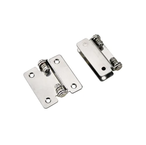
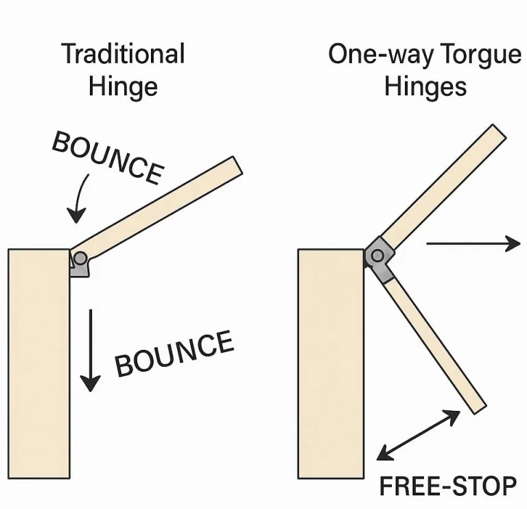
A torque hinge resists rotation around its pivot. In an adjustable design, a screw, nut, cam, preload feature, or another product-specific mechanism changes the preload applied to the internal friction interfaces. More preload generally increases rotational resistance; less preload reduces it.
That distinction matters because an adjustable torque hinge is not simply a free-swing hinge with a brake added later. The adjustment mechanism is part of the torque-producing structure, and the usable range depends on the actual product design.
A fixed-torque hinge arrives with a supplier-defined resistance level that is not intended to be changed during normal setup. An adjustable hinge gives the installer or engineer a defined way to tune the resistance within the model’s available range. Neither architecture is automatically better. The question is whether the application benefits from final tuning or needs a fixed, repeatable configuration.
For fixed-torque, one-way, two-way, and other torque-hinge architectures beyond final resistance adjustment, use the torque hinges overview.
Adjustment Changes Resistance, Not Load Geometry
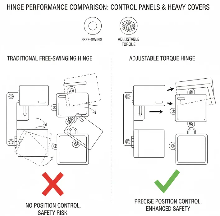
The adjustment feature changes the hinge’s resistance to rotation. It does not change the gravitational moment created by the moving assembly. A heavier panel, a center of gravity farther from the pivot, a new display mounted near the free edge, or a cable harness that pulls during rotation can all increase the required resistance even though the hinge itself has not changed.
Adjustment changes rotational resistance. It does not change panel mass, center of gravity, external cable or spring forces, hinge-axis alignment, mounting stiffness, or the usable range of the selected hinge model.
Detailed torque sizing belongs in the torque hinge selection guide. The adjustable-hinge page only needs the result: the selected model must place the real working condition inside a usable adjustment range, not beyond it.
Adjustable Torque Hinges: Holding vs. Operating Effort
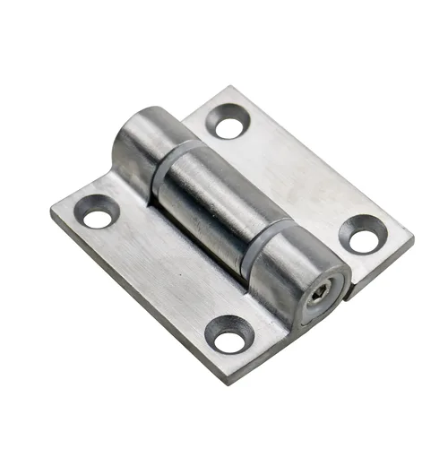
More resistance is not automatically better. The hinge must resist the loads that would move the panel after release, while still allowing the user to reposition the panel without excessive hand force or visible movement in the mounting structure.
Too Loose, Usable, or Too Tight
When resistance is too low, the panel can drift after release or move when a user touches a display. Within a usable range, the panel remains stable but still moves smoothly when intentional hand force is applied. If the resistance is increased too far, the user may need to push harder than the product should require, the bracket may twist, or paired hinges may start to fight each other.
The unwired panel holds. The production panel does not. A control panel is adjusted on the bench and remains stable at the required angle. The production harness is then installed. The cable loop pulls across part of the motion range, and the panel begins drifting. Increasing hinge resistance stops the drift, but the operator now needs noticeably more force and the thin mounting bracket flexes.
The hinge may not be the original problem. The missing cable load and bracket stiffness changed the installed system. Adjustment can compensate only when the final requirement remains inside the hinge and structure’s usable range.
This is an illustrative engineering scenario, not a customer project record or product test claim.
Where Adjustable Torque Helps
Adjustable torque hinges can serve as position control hinges when a lid or panel must remain at useful intermediate positions without a separate locking stay. They are most useful when the final installed configuration has a legitimate setup variable and the selected hinge range still covers the complete moving assembly.
| Moving Part | Why Adjustment May Help | What Still Needs Verification |
|---|---|---|
| Lid or access cover | Fine-tunes the balance between staying open and remaining easy to move | Complete moving mass, CG, final stop, hand point, mounting stiffness |
| Display or operator panel | Allows final setup after the display, bezel, controls, and brackets are assembled | Touch force, viewing positions, bracket flex, cable influence |
| Control or service panel | Accommodates known configuration variation when the selected hinge range covers the final assembly | Harness force, grounding strap, service angle, stop responsibility |
| Inspection panel or instrument cover | Allows the operating feel to be tuned without adding a separate locking stay | Access frequency, user force, common-axis alignment, environment |
Adjustability is less useful when the main requirement is lift assistance, automatic return, soft closing, or a rigid locked-open position. Those are different motion functions and should be compared at the mechanism level rather than forced into an adjustable torque hinge.
When Tightening Stops Being the Fix
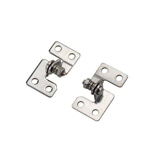
An adjuster near its mechanical limit is a useful warning. If the panel still drifts, or if the assembly becomes difficult to move before stable holding is reached, the engineer should stop treating the problem as a tuning issue.
| Observed Condition | Likely Question | Next Action |
|---|---|---|
| Panel still drops at maximum practical adjustment | Is the selected torque range too low for the complete moving assembly? | Return to model sizing with actual mass, CG, accessories, and hinge quantity |
| Panel holds, but hand force becomes excessive | Is the hinge being used to compensate for another load or geometry problem? | Inspect cables, springs, seals, hand point, and bracket stiffness |
| Resistance changes sharply through part of the motion | Are the hinge axes, brackets, or adjacent parts introducing binding? | Release the suspect constraint and inspect the motion before further adjustment |
| One side of a two-hinge panel feels tighter | Are the hinges aligned and intended to operate as a pair? | Check the common axis and preserve any supplier-defined pair identification |
| Panel held before accessories were installed | Did the real moving load change? | Repeat validation with every production component attached |
| Bracket moves while the panel is operated | Is mounting stiffness becoming the limiting element? | Correct the bracket or frame structure before adding more hinge resistance |
Adjustment should finish a correct selection. It should not rescue a hinge that is outside its usable range or a structure that cannot carry the operating reaction.
Mounting Structure Changes the Result
The hinge may generate the intended resistance while the panel still feels wrong because the surrounding structure moves. Thin brackets can rotate, formed sheet edges can flex, fastener seating can distort a hinge leaf, and coating buildup can change the relationship between two mounting faces.
Watch the assembly while the panel moves. If the bracket twists before the hinge rotates, part of the user’s effort is being spent deforming the structure instead of overcoming hinge resistance. Tightening the adjuster can make that symptom worse.
Paired Hinges Need One Practical Axis
Two adjustable torque hinges on the same lid or panel should not be treated as two independent friction devices. Their pivot axes must be sufficiently aligned for the assembly to rotate without forced side loading. Hole fit alone does not prove that condition.
If the supplier identifies hinges as a matched pair, keep the pair together through assembly and service. The detailed reasons for screening and pair behavior are covered in why some torque hinges require matched pairs.

Set the Hinge Under Real Load
Final adjustment should be performed on the completed moving assembly, not on an empty bracket or partially built panel. The display, handle, trim, wiring, cable retainers, grounding strap, protective cover, and any other item that moves with the lid can change both the static holding requirement and the force felt during motion.
Adjustment access also needs to remain practical after assembly. A model that can be tuned easily on a bench may be difficult to reach once the panel is installed against a frame, side wall, cable bundle, or enclosure return.
- Install the released hinge and the complete moving panel using the intended production mounting structure.
- Move the panel through the usable range before changing the adjustment. Look for binding, bracket movement, cable pull, and contact with adjacent parts.
- Adjust only within the supplier-defined method and accessible range for that hinge design. Do not assume a universal turn count or tool setting.
- Recheck both holding behavior and manual operating effort after each meaningful change.
- Confirm that the final stop, stay, or structural feature carries maximum travel if the hinge is not specifically designed to act as the stop.
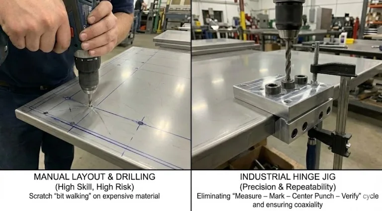
Hole preparation, fastening, alignment sequence, and commissioning still affect the result; use the torque hinge installation guide for the complete mounting procedure.
Validate the Installed Lid or Panel
A successful setup is not defined by one angle or one bench test. The complete assembly should be observed at the positions that matter to the user and service process.
- Holding: the panel remains stable at the required operating positions after release.
- Operating feel: deliberate movement is possible without excessive hand force or abrupt breakaway.
- Structure: brackets, frame returns, and mounting faces do not visibly shift while the hinge rotates.
- Alignment: paired hinges rotate without binding, skew, or one side leading the other.
- Connected hardware: cables, hoses, straps, and harnesses do not pull the panel out of position or become the final stop.
- Travel boundary: the component responsible for maximum opening carries that condition without relying on an unverified internal hinge stop.
- Repeatability: repeated operation does not immediately change the setup or loosen the mounting interface.
Cycle life, torque retention after cycling, environmental drift, and acceptance limits require product-specific test data. They cannot be inferred from the word “adjustable,” and this page does not assign a universal cycle target.
Application Data for Model Review
A useful adjustable-hinge review starts with the moving assembly, not a request for “an adjustable hinge.” Provide the information that determines whether the model has enough usable adjustment range and whether the final structure can support it.
- lid or panel orientation and opening direction;
- complete moving mass, including mounted hardware;
- center-of-gravity location relative to the hinge axis;
- hinge quantity and approximate spacing;
- required operating positions or angle range;
- user hand point and desired operating feel, if defined;
- door, lid, bracket, and frame mounting geometry;
- adjustment access after final assembly;
- cables, hoses, grounding straps, springs, seals, or other forces acting during motion;
- final-stop responsibility;
- operating environment that may affect material or friction behavior;
- required supplier evidence such as drawing, adjustment method, torque range, or available validation data.
Send the Lid or Panel Configuration for Model Review
Send the moving mass, center-of-gravity location, panel orientation, required positions, mounting drawing, hinge quantity, adjustment-access condition, connected cables or straps, and operating environment. Those inputs allow the adjustable range and mounting concept to be reviewed against the actual assembly instead of a generic hinge description.
FAQs
What does an adjustable torque hinge actually adjust?
It changes the rotational resistance generated by the hinge within the model’s available adjustment range. It does not change panel mass, center of gravity, bracket stiffness, cable force, or hinge-axis alignment.
Can an adjustable torque hinge fix an undersized hinge?
Not reliably. If the panel still drifts near the practical end of the adjustment range, or becomes too difficult to move before stable holding is reached, return to model sizing and the complete assembly inputs rather than forcing more adjustment.
Why does a panel still drift after the hinge is tightened?
The installed assembly may include loads that adjustment cannot remove, such as a different center of gravity, cable pull, a grounding strap, bracket flex, axis misalignment, or a hinge range that is too low for the final configuration.
Should two adjustable torque hinges be set the same?
Do not assume that identical adjuster positions guarantee identical installed behavior. The hinges must share a practical axis, the mounting structure must be stable, and any supplier-defined matched pair or adjustment procedure should be preserved. Final acceptance should be based on the complete panel behavior.

 English
  한국어
한국어  Русский
  Español
  Italiano
  Deutsch
  Français
  Português