Torque Hinge Selection Guide: Formula, Examples & N·m Charts
Torque hinges (also called friction hinges or free-stop hinges) introduce controllable damping and holding torque into a rotational joint. They allow a lid, cover, display, or door to hold position at a chosen angle without spring-back, while also delivering a smoother and more controlled user experience during opening and closing.
In laptops, industrial service doors, medical display arms, equipment covers, and precision instruments, torque hinges directly affect safety, usability, product lifetime, and perceived quality. A poorly selected hinge may cause sagging, difficult operation, torque fade, or sudden panel drop. A correctly selected hinge improves stability, ergonomics, and long-term reliability.
This guide explains the basic physics of torque hinges, how to calculate required holding torque, how to choose the right hinge type, what materials perform best in different environments, and how to avoid common engineering mistakes in real projects.
Basic Principles of Torque Hinges
Definition and Physical Meaning
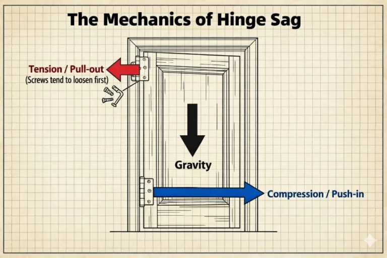
Torque is rotational force. In hinge selection, the basic principle is simple: gravity creates a turning force on the panel, and the hinge must generate enough resisting torque to balance it.
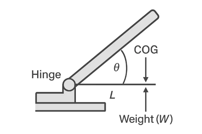
The most basic relationship is:
T = F × L
Where:
- T = torque, in N·m
- F = force, in Newtons
- L = perpendicular distance from the hinge axis to the center of gravity
In real hinge structures, the panel’s weight creates a gravitational moment, and the hinge’s internal friction mechanism creates a resisting torque. When hinge torque is equal to or greater than the disturbing torque, the panel can hold position reliably.
Static Torque vs. Dynamic Torque
When selecting a torque hinge, it is essential to separate static torque from dynamic torque.
- Static torque: the torque required to hold the panel stationary at a given angle
- Dynamic torque: the torque required to move the panel during opening or closing
For holding-position design, static torque is the primary value. Dynamic torque matters for user feel, movement smoothness, and the effort required to reposition the panel.
In many products, static torque and dynamic torque are not identical. Some hinges have a higher starting resistance and a slightly lower running resistance. This is one reason why a hinge that looks correct on paper can still feel wrong in actual use if the torque curve is not understood properly.
Working Mechanism
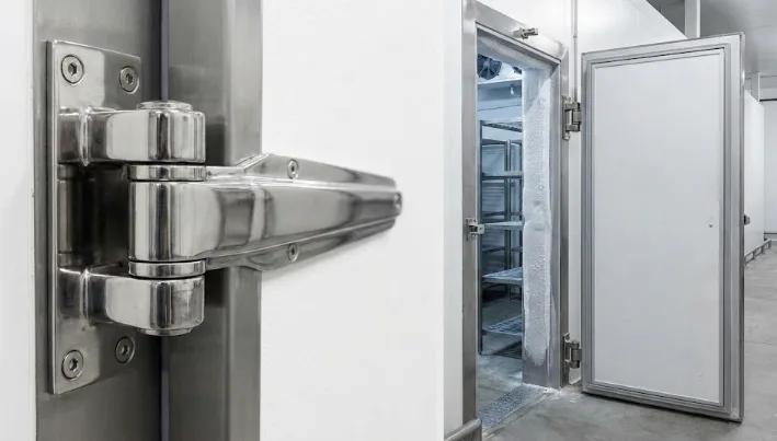
Internally, torque hinges rely on friction pairs, preload, and contact pressure to create consistent resistance. Typical internal constructions use steel, stainless steel, bronze, polymer friction elements, or preloaded elastic parts to generate near-constant damping.
The design goal is simple: the hinge should resist unwanted motion caused by gravity, vibration, or minor external disturbance, while still allowing intentional repositioning by the user.
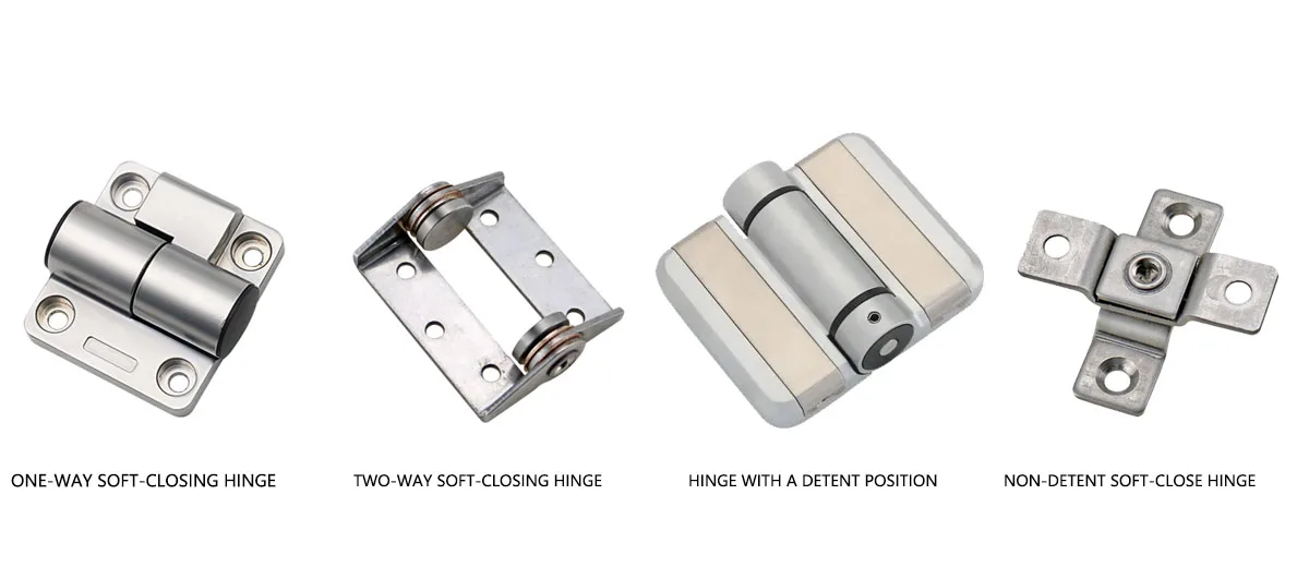
Classification by Structural Form
Key Parameters for Torque Hinge Selection
| Type | Description | Typical Application |
|---|---|---|
| Unidirectional | Provides damping mainly in one direction | Heavy maintenance lids, top-opening covers |
| Bidirectional | Provides controlled resistance in both directions | Laptop screens, medical monitors, HMI panels |
| Adjustable | Allows torque to be tuned during assembly or maintenance | Prototyping, equipment with variable load requirements |
| Constant Torque | Provides consistent free-stop resistance across the motion range | Consumer electronics, equipment doors, access panels |
Basic Quantities Needed
- Mass: measured in kg
- Weight: calculated in Newtons
- Lever arm: the perpendicular distance from hinge axis to the center of gravity
- Angle: the panel position relative to gravity
- Hinge count: the number of hinges sharing the load
The first critical rule is this:
Do not calculate from kg directly. Convert mass to force first.
The correct conversion is:
Weight (N) = Mass (kg) × 9.81
The Core Selection Formula
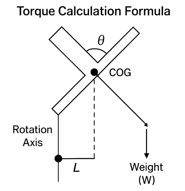
For hinge holding calculations, the design requirement can be written as:
T_required = Weight × Lever Arm × sin(angle)
In most practical hinge applications, the worst-case condition occurs when the panel is horizontal, because gravity has the largest effective lever arm at that point. In that case:
T_peak = Weight × Lever Arm
To make the design safe for real-world use, a safety factor should then be applied:
T_design = Safety Factor × T_peak
For most industrial applications, a practical safety factor is:
Safety Factor = 1.2 to 1.5
This accounts for wear, torque decay, assembly bias, environmental changes, and unexpected handling loads.
Common Pitfalls
- Using kg instead of Newtons
- Assuming the geometric center is always the center of gravity
- Ignoring the worst-case angle
- Assuming two hinges always share load perfectly equally
For asymmetrical panels, panels with accessories, or panels carrying handles, fans, monitors, or reinforcement structures, always confirm the true center of gravity in CAD before final hinge selection.
Where two hinges are intended to work together, matched hinge pairs are strongly recommended to reduce load imbalance and inconsistent movement feel.
Calculation Examples by Application
Laptop Display Example
Assume:
- Display mass = 0.45 kg
- Weight = 0.45 × 9.81 = 4.41 N
- Lever arm = 0.10 m
Then:
T_peak = 4.41 × 0.10 = 0.441 N·m
With a safety factor of 1.3:
T_design = 0.441 × 1.3 = 0.57 N·m
If two hinges are used, each hinge should typically be sized around:
0.29 N·m per hinge
For medical monitors, imaging devices, and diagnostic equipment, see our more specific guide to torque hinge selection for medical devices.
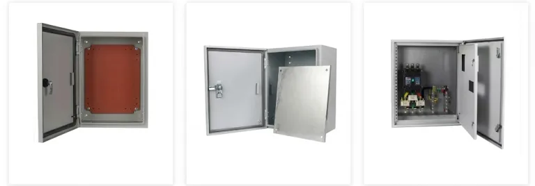
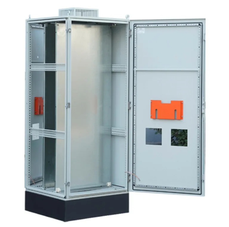
Industrial Service Cover Example
Assume:
- Steel cover mass = 3.0 kg
- Weight = 3.0 × 9.81 = 29.43 N
- Lever arm = 0.18 m
Then:
T_peak = 29.43 × 0.18 = 5.30 N·m
With a safety factor of 1.3:
T_design = 5.30 × 1.3 = 6.89 N·m
With two hinges:
About 3.45 N·m per hinge
For high-vibration environments, such as compressors, generators, or mobile equipment, the safety factor should be increased further.
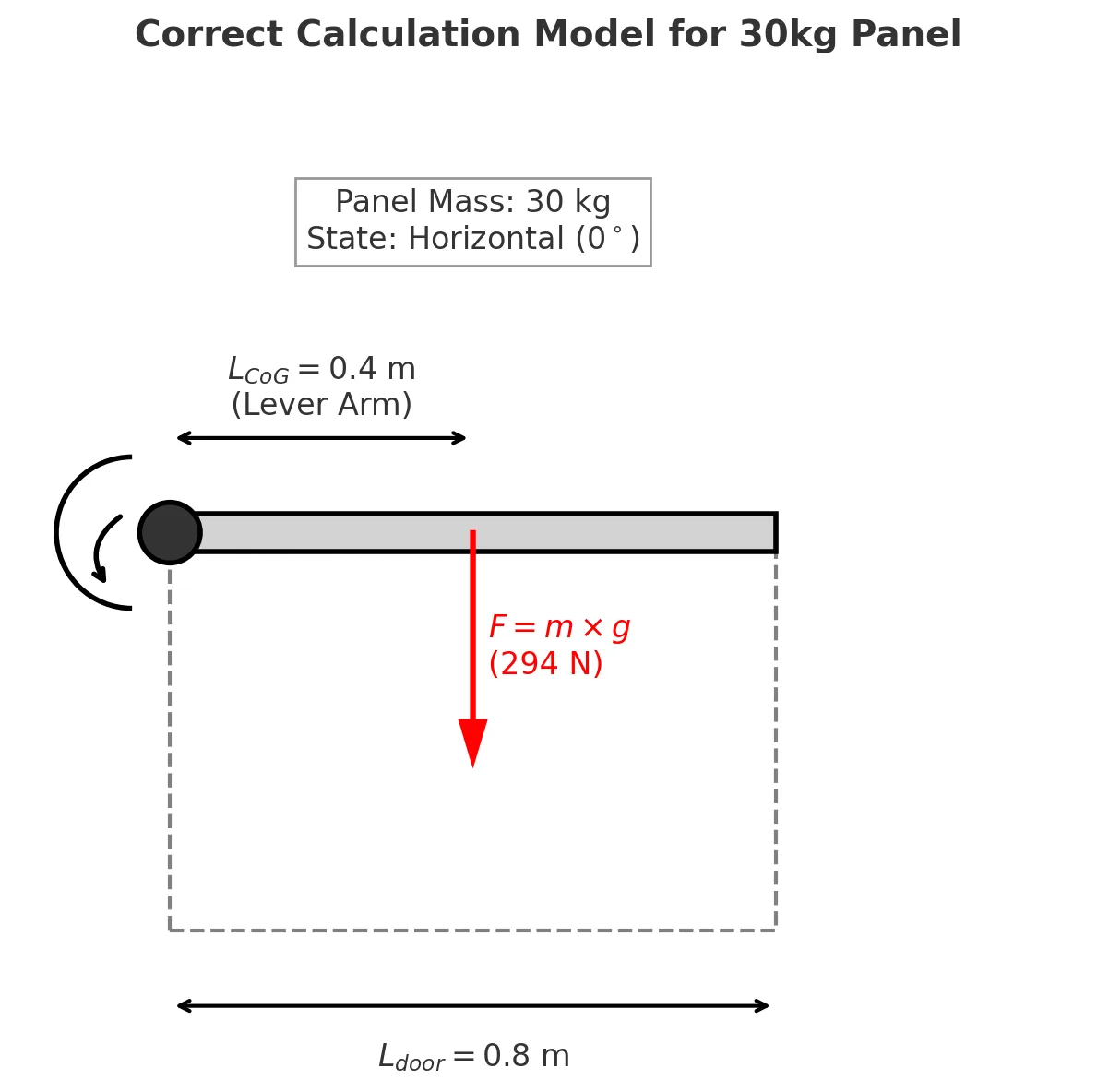
Worked Example: 30 kg Top-Opening Panel
This is the most useful kind of real engineering example because it shows where many heavy-panel selection errors begin.
Assume you are designing a top-opening maintenance lid for an industrial outdoor cabinet or equipment enclosure.
- Panel mass = 30 kg
- Panel length = 0.8 m
- Center of gravity assumed at half length = 0.4 m
- Panel must hold between 0° and 90°
First convert mass to force:
Weight = 30 × 9.81 = 294.3 N
Then calculate peak torque at the horizontal position:
T_peak = 294.3 × 0.4 = 117.72 N·m
This means the hinge system must provide at least about 117.7 N·m to hold the lid from dropping when horizontal.
Now apply a practical industrial safety factor:
T_design = 117.72 × 1.2 = 141.26 N·m
If two hinges share the load:
Torque per hinge = 141.26 ÷ 2 = about 70.6 N·m
Peak torque is determined by panel weight, center of gravity distance, and the worst-case opening position.
This is already in the super-heavy-duty range. In real projects, a pure friction-hinge-only solution at this level may make the lid too difficult to operate. That is why many heavy lids use a hybrid design, such as torque hinges plus gas struts or stays, so the gas strut handles most of the gravity load while the hinge provides controlled positioning.
Top-Opening vs Side-Swing: Why Orientation Changes Everything
One of the most common mistakes in hinge selection is assuming that a 30 kg panel always requires the same torque regardless of installation direction. It does not.
Top-Opening Lid
For a top-opening lid, gravity continuously acts to pull the panel downward through the full motion range. That means the hinge system must resist almost the full gravitational torque. This is the worst case for holding torque selection.
In this orientation, the full calculated torque is relevant.
Side-Swing Panel
For a side-swing panel rotating around a vertical axis, gravity acts mainly as a downward load, not as a large rotational moment around the hinge axis. In many such cases, the torque hinge is used more for movement feel, anti-slam behavior, or wind resistance than for true gravity holding.
As a rule of thumb, side-swing applications may only need about 10% to 20% of the torque required for a top-opening panel of the same mass and size, depending on the exact geometry and user requirement.
This is why installation orientation must always be defined before hinge selection starts.
Common Heavy-Panel Calculation Mistakes
Ignoring Accessory Weight
Many designers calculate only the bare metal panel and forget the real assembly. Once gaskets, stiffeners, cable trays, handles, monitor brackets, or other mounted components are added, the actual center of gravity shifts and the total weight increases.
Always perform the final torque review after the bill of materials is frozen, not before.
Confusing Static and Dynamic Torque
A hinge may hold well when stationary but still feel unstable during movement if the dynamic torque drops sharply after breakaway. This can cause the panel to accelerate unexpectedly once motion begins.
Always review both holding performance and movement behavior, especially for user-facing equipment or large lids.
Material Mismatch
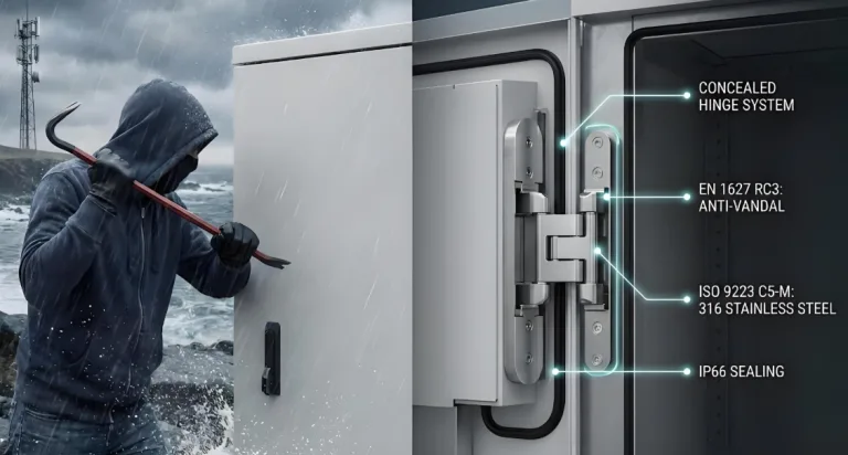
Using standard carbon steel hinges in coastal, chemical, or outdoor environments often leads to corrosion, rising friction, seizure, and premature torque loss. For harsh environments, material selection is not a minor detail. It is part of the torque stability strategy.
Where corrosion resistance is critical, review the application against the torque hinge material guide and prioritize stainless steel or properly protected alloys. If you are weighing cost against durability, our breakdown of when to choose stainless steel over carbon steel walks through the trade-offs for each environment.
Materials and Environmental Durability
| Material | Advantages | Risks and Notes |
|---|---|---|
| Stainless Steel 304 / 316 | High strength and corrosion resistance | Higher cost, galling risk if pairing is not designed well |
| Aluminum Alloys | Lightweight and easy to machine | Lower surface hardness, often needs anodizing |
| Engineering Plastics | Low friction, quiet operation, lightweight | Thermal drift and creep must be considered |
| Carbon Steel with Surface Protection | Cost-effective and strong | Not ideal for harsh outdoor or corrosive environments without proper protection |
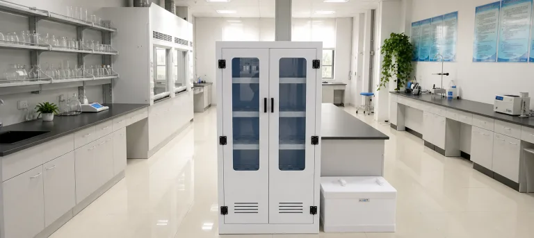
For outdoor, medical, food, or coastal applications, environmental durability is as important as nominal torque rating. Corrosion, heat, low temperatures, and chemical exposure all affect long-term torque stability.
Selection Workflow
- Define the installation orientation and motion range
- Measure the real mass and center of gravity of the final assembly
- Calculate peak torque at the worst-case angle
- Apply a safety factor of 1.2 to 1.5
- Divide the load across the actual number of hinges, while remembering real sharing is never perfectly equal
- Select hinge type and torque range
- Verify material and environment compatibility
- Prototype test the system for feel, hold, and temperature behavior
If your project requires more detailed multi-scenario examples, refer to How to Calculate Torque Hinge Requirements: Industry Case Studies.
Installation and Alignment Guide
Correct installation is just as important as correct selection. Even a correctly rated hinge can fail early if misalignment, side loading, or improper fastening distorts the housing or shifts the hinge axis.
- Mounting surfaces should be flat and rigid
- Multiple hinge axes must remain co-linear
- Fastener torque must be controlled to avoid housing distortion
- Thread-locking compounds may be needed in high-vibration applications
For applications requiring tunable resistance, see adjustable torque hinges for principles, field setup, and adjustment behavior.
Maintenance and Service Life
Torque hinge life depends on load, cycle frequency, temperature, environment, and maintenance quality. Standard-grade hinges may perform well in moderate conditions, but premium industrial hinges with hardened shafts and advanced friction elements are more suitable for high-cycle or harsh-duty applications.
Typical inspection points include:
- surface corrosion
- mounting-hole cracking
- uneven torque feel
- torque fade over time
- fastener loosening
In critical equipment, actual torque should be checked periodically, especially when the panel must hold safely under repeated use. If your main concern is long-term torque fade, wear, or reliability drift, review our technical guide on why torque hinges lose strength and how to prevent it.
Troubleshooting Guide
| Symptom | Likely Cause | Corrective Action |
|---|---|---|
| Panel will not hold position | Torque under-calculated, safety factor too low, or internal wear | Recalculate and select a higher torque range |
| Operation feels too heavy | Torque oversized or breakaway torque too high | Reduce hinge torque or introduce gas strut assistance |
| Torque fades over time | Wear, heat, or lubricant degradation | Review hinge construction and service life data |
| Resistance changes with temperature | Grease viscosity drift or material expansion | Use more temperature-stable hinge design |
| Uneven resistance across motion | Misalignment or internal damage | Check installation geometry and replace if necessary |
Typical Torque Reference Ranges
- Small electronics: 0.1 to 0.6 N·m
- Laptops: 0.4 to 0.8 N·m per hinge
- Medical or POS displays: 1.5 to 5.0 N·m
- Industrial cabinets and equipment doors: 5.0 to 15.0 N·m
- Heavy machinery hatches and lids: 20.0 N·m and above, often with counterbalance support
FAQ
Q1: Should I use mass or weight for torque hinge selection?
Always use weight in Newtons. Convert from kg using: Weight = Mass × 9.81.
Q2: Why does peak torque usually occur when the panel is horizontal?
Because the effective lever arm of gravity is largest in that position, which creates the maximum gravitational moment around the hinge axis.
Q3: Can two hinges share load perfectly equally?
No. Manufacturing tolerances, assembly bias, and installation differences always affect real load sharing. That is one reason a safety factor is required.
Q4: Can torque hinges replace gas struts?
For smaller and medium loads, yes. For very heavy lids, a combined solution may work better. See Torque Hinges vs Gas Springs vs Springs for a deeper comparison.
Q5: What is the typical service life of a torque hinge?
It depends on load, cycle count, material, temperature, and design quality. Standard products may be rated for 10,000 to 25,000 cycles, while higher-end industrial hinges can exceed 50,000 cycles when properly specified.
Q6: When should I use matched hinge pairs?
Whenever two hinges are expected to share load and movement feel consistently, matched pairs are strongly recommended.
Conclusion
Torque hinge selection is not just about choosing a nominal torque value from a catalog. It requires understanding gravity, center of gravity location, motion orientation, safety factor, real load sharing, environmental conditions, and long-term durability.
For lightweight screens, moderate equipment doors, and heavy industrial lids, the same physics principle applies: calculate the real peak torque, apply a realistic safety factor, and match the hinge system to the actual application rather than the theoretical minimum. When this process is done correctly, the result is a safer, smoother, and more durable product.