

How to Select Torque Hinges for Medical Devices
A medical display can stay at 45° on a bench and still move when a user taps the screen. A lid can meet the nominal torque calculation and still drift at another angle. The drawing may fit. The assembled device can still bind.
Those failures occur because torque hinge selection for medical devices is not a one-number exercise. The hinge has to balance the real moving mass, hold through the working angle, feel predictable to the user, tolerate the actual cleaning process, and retain enough function after cycling and environmental exposure. The complete device—not the loose hinge—decides whether the selection works.
Scope: This guide covers medical and laboratory equipment that needs a display, lid, cover, or panel to remain at a selected angle. For broader hinge placement across carts, instrument doors, cabinets, and removable service panels, use the medical and laboratory equipment hinge solution.
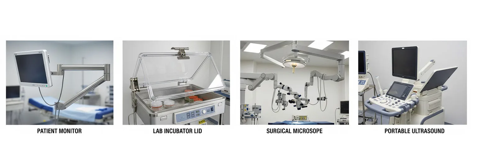
Medical position-control requirements change with the moving assembly, user interaction, cleaning process, and consequence of drift or drop.
Position Holding or Lift Assistance?
Start with the motion the device must provide. A torque hinge is appropriate when the user needs to move a panel and leave it at an intermediate angle without a separate stay. It is not automatically the right answer for every medical lid or display.
| Required Behavior | Mechanism Direction | Why | Main Medical-Device Check |
|---|---|---|---|
| Free pivot with no intermediate holding | Standard hinge | The door or cover only needs rotation; a latch, stay, or user controls the position | Opening stop, pinch points, latch, alignment, and safe service access |
| Stay at many user-selected angles | Torque or position-control hinge | Internal resistance holds the panel without a separate support member | Spring-back, user force, drift, cleaning exposure, and retained torque |
| Reduce the force required to raise a heavy lid | Gas spring, mechanical spring, counterbalance, or assisted hinge | The primary need is positive lift assistance rather than frictional holding | Force through travel, closing force, space, failure safety, and service support |
| Lift assistance plus intermediate holding | Hybrid system | One mechanism offsets part of the load while another stabilizes the selected position | Interaction between assist force, holding resistance, stops, and user effort |
| Multi-axis display adjustment | Multi-axis joint or arm with torque elements | A single hinge axis cannot provide the required range of motion | Touch stability, cable path, joint play, cumulative backlash, and reach envelope |
A torque hinge resists motion; it does not create the same positive lift force as a gas spring. Increasing hinge torque to compensate for a heavy lid can stop drift but make the device unpleasant or unsafe to operate. That is a mechanism conflict, not a supplier-quality issue.
Motion Quality at the User Interface
Holding torque is only one part of the user experience. A clinician repositioning a screen, or a technician opening an analyzer lid, feels the difference between starting motion, continuing motion, releasing the panel, and touching the device after it has been positioned.
| Motion Characteristic | What the User Notices | What to Define | What to Measure on the Device |
|---|---|---|---|
| Breakaway behavior | A jerk or sudden release when movement starts | Allowed peak force or torque at the start of motion | User force at the actual grip point and starting angle |
| Running behavior | Heavy, light, or uneven movement through travel | Acceptable force range in both directions | Force or torque across the required angular range |
| Spring-back | The display or lid rebounds after the user lets go | Maximum acceptable angle change after release | Released position versus settled position |
| Backlash and free play | The screen feels loose during touch input or direction reversal | Allowable movement before resistance is re-established | Display-edge displacement or angular play under a defined input |
| Touch stability | The display moves while the user operates the touchscreen | Expected touch force, direction, and point of application | Panel displacement and recovery under representative user input |
| Direction balance | Opening feels different from closing | Symmetric or intentionally asymmetric resistance | Separate opening and closing measurements |
A screen can pass a static hold test and still fail touch stability. The static load may be balanced, yet the user applies force far from the hinge axis. The extra moment briefly exceeds the available holding resistance and the screen moves. This is why the acceptance method needs the real input point, not only a torque reading from a loose component.
Load Moment From the True Center of Gravity
The gravitational moment around the hinge axis is the starting point for sizing:
Mload(θ) = W × d⊥(θ)
W is the weight of the complete moving assembly. d⊥(θ) is the perpendicular distance from the hinge axis to the gravity line at angle θ. Depending on how the angle is defined, the same relationship may be written with a sine or cosine term. The drawing and test report must state the angle reference; otherwise two correct calculations can appear to disagree.
Use the true center of gravity, including the display, battery, heat sink, wiring, protective glass, handle, internal brackets, and any part that moves with the panel. The geometric center is only correct when the mass distribution supports that assumption.
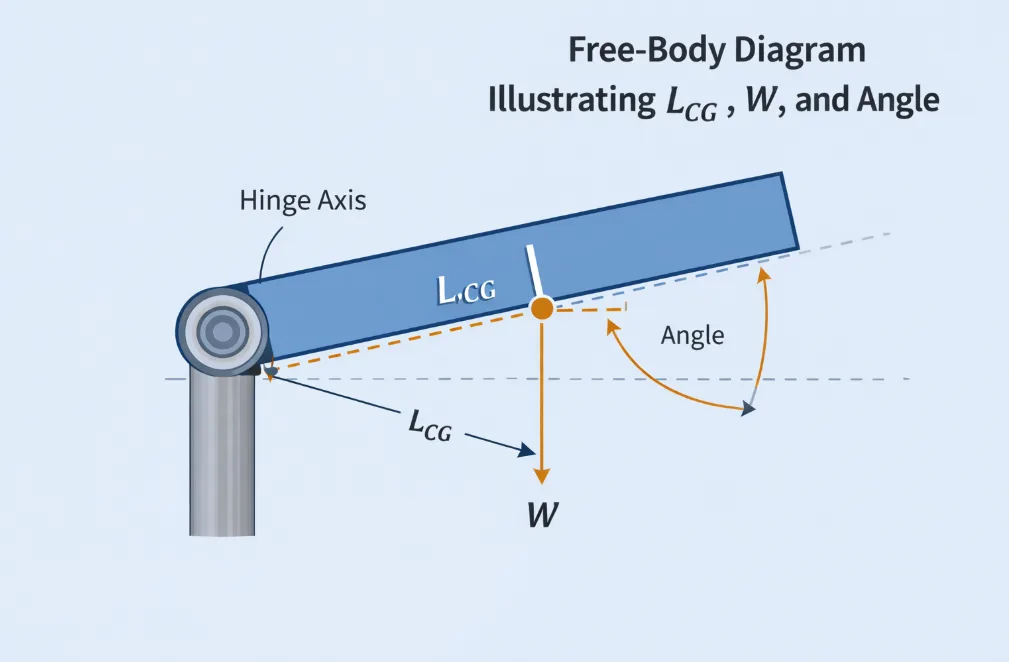
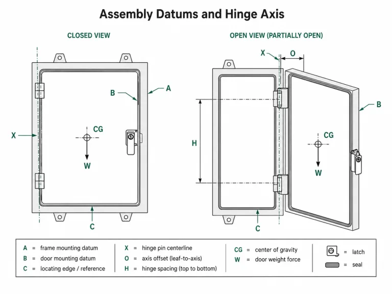
The diagram is illustrative. Define the angle reference and use the actual center of gravity of the moving assembly.
More Than Gravity Loads the Hinge
For an adjustable display, gravity is not the only input. Touch force, cable resistance, flexible seals, detents, latches, and movement stops can add or subtract moment at different angles. A top-opening analyzer lid may also carry a handle load or local user force that the basic gravity calculation does not include.
When several hinges are used, an initial estimate may divide the total required resistance by the hinge count:
Thinge(θ) ≈ Mload(θ) / N
That is only a preliminary estimate. It assumes the leaves are aligned, the mounting structure is sufficiently stiff, and the units share the load reasonably. Do not embed a universal 0.5 coefficient for every two-hinge medical display. Production variation, sheet-metal distortion, bracket stiffness, and axis error can make one hinge carry more of the functional load.
The general torque hinge selection guide covers broader orientation and calculation cases. This medical page stays focused on the inputs that affect user interaction and validation.
The Full Torque-Angle Range
A catalog torque value does not describe the complete motion. Medical-device engineers need to know how resistance behaves at the angles that matter: closed, initial opening, working positions, maximum opening, and return.
- Holding points: identify every angle where the display, lid, or cover must remain stable.
- Opening and closing direction: record them separately when the mechanism is asymmetric.
- Lowest delivered resistance: a lower-end sample may drift even when the nominal rating matches the calculated moment.
- Highest delivered resistance: a higher-end sample may meet holding requirements but exceed the acceptable user force.
- Breakaway and running relationship: a large difference can produce stick-slip movement even when the average torque looks acceptable.
- Settled position: measure the panel after release, not only while the user is still holding it.
Engineering conflict: A display with an offset battery can hold near its maximum open angle yet drift through the middle of travel. Selecting a much stronger hinge may stop the drift but make one-hand adjustment and touchscreen positioning too heavy. The correct fix may involve a different torque curve, center-of-gravity change, hinge location, assisted mechanism, or matched pair—not simply a larger nominal value.
This is an illustrative engineering scenario, not a customer project record or product test claim.
Mounting Geometry and Paired Hinges
The hinge can meet its loose-part specification and still feel wrong after installation. Torque hinges are sensitive to the structure that holds their axes.
One Axis, Two Mounting Surfaces
Both mounting faces need to place the hinge pin centerline where the design expects it. If the brackets twist the leaves, the friction mechanism may carry assembly preload in addition to the panel moment. Movement becomes heavy, uneven, or noisy. The problem can disappear when the hinge is removed from the device, which makes it easy to misclassify as a torque-quality issue.
Matched Output Is Not Enough
Two hinges intended to share a wide display should be reviewed as a pair, but matched torque values alone do not correct different mounting stiffness or axis error. Measure the assembled panel for free play, running force, release angle, and left-to-right movement. Watch for one bracket moving before the other.
Cable and Stop Loads
Display cables routed near the pivot can create angle-dependent resistance. A harness may assist movement in one direction and oppose it in the other. Hard stops should arrest the device structure, not force the internal torque element to absorb uncontrolled overtravel. Review the cable bend radius, connector strain, stop contact, fastener access, and service sequence before freezing the hinge position.
Cleaning Exposure Inside the Hinge
“Indoor medical use” does not define the environment. The selection input is the cleaning process: agent, concentration, contact time, wipe frequency, rinse or dry condition, temperature, and whether liquid can reach the pin, fasteners, friction elements, lubricant, and hidden joints.
| Exposure Input | Hinge Area Affected | Possible Change | Evidence to Request or Generate |
|---|---|---|---|
| Repeated surface wiping | Leaf finish, fasteners, edges, labels, external joints | Discoloration, coating wear, residue, exposed substrate | Actual cleaner, concentration, wipe method, visual and functional result |
| Cleaner entering the pivot | Pin, bushing, friction washer, spring, lubricant | Corrosion, lubricant removal, swelling, torque rise, torque loss, seizure | Representative exposure followed by the original movement test |
| Mixed metals | Leaf, pin, fastener, bracket, washer | Galvanic or crevice attack in retained moisture | Complete material stack, drainage condition, surface treatment |
| Polymer contact | Bushings, seals, covers, nearby PC or ABS components | Stress cracking, swelling, softening, particulate generation | Supplier compatibility data and device-level exposure test |
| Lubricant migration | Pivot, nearby cosmetic or optical surfaces | Oil bleed, contamination, changing torque, dust collection | Conditioning data, temperature range, material compatibility, inspection method |
| Moisture or condensation | Hidden fastener pockets, pin ends, enclosed brackets | Internal corrosion and changing movement before visible surface damage | Drainage review and post-exposure functional retest |
Do not select 304, 316, aluminum, zinc alloy, polymer, coating, or passivation from a universal ranking table. The exposed surface may survive while the pin, fastener, spring, friction element, or lubricant does not. Material grade is one part of the system; the cleaning method and joint geometry complete the decision.
Drift, Seizure, and Torque Decay
The three failures look different to the user and point to different evidence. Treating all of them as “wrong torque” usually leads to the wrong corrective action.
| Observed Behavior | Likely Engineering Branches | Evidence to Inspect | Corrective Direction |
|---|---|---|---|
| Panel slowly drifts after release | True moment exceeds delivered resistance, torque distribution is uneven, spring-back settles the panel, cable force changes with angle | Actual mass and CG, torque-angle data, released angle, pair output, cable path, mounting stiffness | Correct the load model, torque curve, axis location, pair selection, cable route, or mechanism architecture |
| Movement becomes heavy or seizes | Corrosion, cleaner ingress, lubricant change, bushing swelling, misalignment, excessive assembly preload | Cold and warm movement, internal and external corrosion, mounting-face flatness, cleaner path, lubricant condition | Remove the exposure or alignment cause; then change the material system, interface, seal, drainage, or mounting design as required |
| Holding force declines with use | Friction-surface wear, preload relaxation, lubricant migration, material creep, thermal effects, accelerated-test distortion | Initial, intermediate, and final torque or user force under the same method; wear and temperature data | Revise the friction system, preload, materials, process control, cycle profile, or acceptance requirement |
| One direction feels rougher | Axis error, directional friction, cable bias, surface scoring, inconsistent paired units | Separate opening/closing curves, hinge removed versus installed, bracket movement | Separate component behavior from assembly-induced loading before changing the torque specification |
| Display holds until touched | Static balance is adequate but touch moment exceeds resistance or bracket stiffness is low | Touch point, force direction, display-edge displacement, bracket deflection | Improve touch stability through resistance, geometry, structure, support, or multi-axis architecture |
Validation Under Real Use
A cycle total is not an acceptance criterion. It is one test input. The useful result is how the medical-device function changes after the defined movement, load, cleaning, temperature, humidity, vibration, or storage conditions.
- Establish the baseline. Record installed opening and closing force, holding angles, released position, spring-back, free play, touch stability, noise, and visible alignment.
- Use the representative assembly. Include the released panel mass, center of gravity, brackets, fasteners, cable route, stops, latch, gasket, and enclosure stiffness where they affect the hinge.
- Define the cycle profile. State the angle range, direction, speed, dwell, load, temperature, maintenance condition, and measurement intervals. Avoid using a convenient motor speed without checking whether heat or inertia changes the failure mechanism.
- Apply the actual exposure. Use the approved cleaner, concentration, wiping or contact method, drying condition, and exposure frequency required by the project.
- Repeat the same functional test. Before-and-after results are only comparable when the fixture, direction, temperature, conditioning, force point, and measurement method remain controlled.
- Inspect the complete load path. Review hinge internals where appropriate, but also inspect leaves, brackets, fasteners, frame, cable supports, opening stops, and the panel structure.
- Judge the retained device function. Acceptance limits for drift, user force, torque loss, free play, corrosion, noise, or spring-back must come from the device requirement or an approved test plan—not a universal percentage copied from another hinge.
Use the torque hinge sample testing checklist when the project is ready to define the fixture, direction, data fields, and sample-approval record in more detail.
Mechanical Safety in the Finished Device
IEC 60601-1 applies to the finished medical electrical equipment, not to a torque hinge as a standalone certified component. The hinge can still influence the device-level mechanical assessment because it affects movable-part stability, uncontrolled closure, pinch points, user-applied force, and access during service.
- Uncontrolled drop: determine what happens if holding resistance decreases or the panel is released at the worst angle.
- Pinch and crush zones: review the complete closing path, not only the hinge knuckle.
- Opening stops: prevent users or service personnel from forcing the internal torque element beyond the designed travel.
- Touch and operating force: enough resistance for stability can become excessive force for the intended user population.
- Service support: a torque hinge is not automatically a safe maintenance prop for a heavy cover. Define a separate support or lockout when service requires it.
- Failure behavior: the device design should address drift, seizure, free play, or loss of holding force rather than assuming the hinge will retain day-one behavior indefinitely.
The hinge selection supports the completed equipment assessment. It does not replace the manufacturer’s usability, risk-management, cleaning, electrical-safety, or regulatory validation.
Application Priorities
| Medical or Laboratory Assembly | Primary Motion Requirement | Failure That Matters Most | Representative Validation |
|---|---|---|---|
| Diagnostic or patient display | Low spring-back, stable touch input, smooth one-hand repositioning | Drift, excessive user force, backlash, cable-induced movement | Installed touch-force and angle-hold test through the working range |
| Analyzer or incubator lid | Controlled hold without obstructing sample access | Drop, seizure, cleaning ingress, torque decay | Complete lid load, handle force, cleaning exposure, and repeated opening |
| Centrifuge or heavy top cover | Safe opening and service access, often with assistance | Excessive lift force, uncontrolled closure, misalignment, corrosion | Mechanism-level test including assist device, stops, latch, and service support |
| Medical cart display | Stable adjustment during movement and repeated use | Vibration-related movement, bracket flex, cable fatigue, changing feel | Installed cart test with representative movement, touch, and cable routing |
| Microscope or multi-axis operator interface | Precise positioning across several joints | Cumulative backlash, joint interaction, touch instability | Complete arm or joint-stack test rather than one hinge in isolation |
| Service cover | Controlled access and repeatable closure | Unsafe support, interference, latch misalignment, fastener movement | Open, hold, service, close, and latch sequence on the assembled equipment |
Data for Model and Sample Review
Do not start with “medical hinge, 2 N·m” and expect the model number to settle the design. Prepare the moving assembly and acceptance inputs first:
- Moving assembly: dimensions, complete mass, true center of gravity, attached cables, handles, glass, brackets, and moving accessories.
- Motion: hinge orientation, opening direction, required angle range, hold positions, opening and closing behavior, and any intentional asymmetry.
- User interaction: grip point, expected hand force, touch-screen force, one-hand requirement, allowable spring-back, allowable free play, and operating population.
- Hinge arrangement: quantity, spacing, axis position, left/right hand, bracket material and thickness, fasteners, available envelope, and required matched-pair condition.
- Other loads: cable resistance, gasket or seal load, latch, detent, opening stop, assisted mechanism, and vibration from a mobile cart or equipment movement.
- Cleaning process: cleaner name, concentration, contact or wipe method, frequency, rinse/dry condition, temperature, and potential access to the pivot.
- Environment: operating and storage temperature, humidity, condensation, contamination, corrosion exposure, and transport or mobile-equipment vibration.
- Life profile: expected movement count, angle, speed, dwell, load, cleaning intervals, maintenance condition, and consequences of drift, seizure, or drop.
- Acceptance evidence: torque-angle or user-force data, released angle, spring-back, free play, touch stability, environmental retest, cycle retention, and installed photographs.
- Commercial inputs: annual quantity, prototype timing, existing or new tooling, drawing status, required material documents, and requested sample quantity.
After these inputs are prepared, review the available torque hinge families by structure, orientation, range, material direction, and available validation evidence. A preliminary recommendation still needs an installed sample test before production approval.
Send HTAN the panel drawing, moving mass, true center of gravity, angle range, cleaning process, motion-quality targets, and sample evidence required. The review can then focus on suitable hinge architecture and the data that still needs to be verified on the finished assembly.
FAQs
How do I calculate torque for a medical device hinge?
Start with the complete moving weight and the perpendicular distance from the hinge axis to the true center of gravity at each relevant angle. The total gravity moment is Mload(θ) = W × d⊥(θ). Dividing by hinge quantity is only a preliminary estimate when the mounting structure and hinge alignment support reasonable load sharing. Add touch force, cable resistance, seals, latches, and other angle-dependent loads separately.
What causes a medical display to drift after adjustment?
Possible causes include an incorrect center of gravity, insufficient resistance at the drifting angle, spring-back, uneven paired hinges, bracket flex, mounting-axis error, cable force, or torque loss after use. Measure the released angle and complete installed system before increasing the nominal torque.
How should cleaning chemicals be included in medical hinge selection?
Define the actual cleaner, concentration, contact time, wipe or immersion method, frequency, rinse or drying condition, and whether liquid can reach the pin, bushing, friction elements, lubricant, fasteners, or nearby polymers. Then repeat the original functional test after representative exposure. A material name alone does not prove compatibility.
Does IEC 60601-1 certify a medical torque hinge?
No. IEC 60601-1 applies to the finished medical electrical equipment rather than certifying a torque hinge as a standalone component. Hinge behavior can still affect the device-level assessment of movable-part stability, uncontrolled closure, pinch points, operating force, and service access.
When is a gas spring or hybrid system better than a torque hinge?
Use lift assistance when the primary problem is the force required to raise a heavy lid. A torque hinge is better when intermediate position holding is the main task. A hybrid can be appropriate when the device needs both load assistance and stable intermediate positions, provided user force, closing behavior, stops, space, and failure safety are validated together.


 English
  한국어
한국어  Русский
  Español
  Italiano
  Deutsch
  Français
  Português