

Hinge Spacing for Long Industrial Doors: Load Distribution and Frame Stiffness
On a long industrial door, “use three hinges” is not a load calculation. A tall, narrow door and a shorter, wider door can have the same mass and hinge count while placing very different reactions into the upper mounting zone. The difference comes from the assembled center of gravity, its distance from the hinge axis, the effective spacing between support zones, and the stiffness of the door and frame.
A defensible approach to hinge spacing for long industrial doors starts with the load path. Establish the door weight and center of gravity, use static equilibrium to estimate the force couple at the hinge line, then decide whether the selected mounting zones are stiff enough to develop those reactions. Only after that should a hinge model, fastener group, weld detail, or prototype be approved.
This page focuses on side-hinged industrial doors supported by two or more discrete hinges. It does not provide a universal spacing rule or a per-hinge catalog rating. Both would require the actual door, mounting structure, service loads, supplier data, and validation criteria.
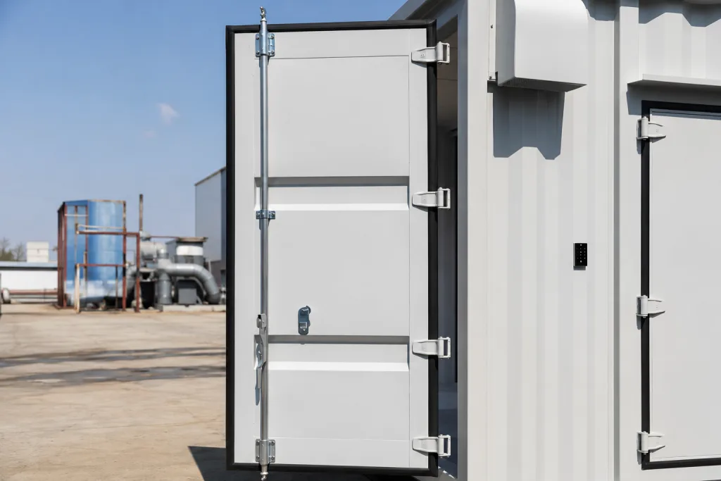
Begin With the Assembled Door
Door height is only one input. Door width controls how far the mass acts from the hinge line, while the vertical separation between the upper and lower support zones controls the force couple available to resist that moment. Door-mounted HMI panels, windows, locks, insulation, stiffeners, guards, and cable hardware can change both mass and center of gravity after the bare panel has been weighed.
Use the final assembly or a controlled mass estimate. The hinge axis must also be defined in the installed condition. An external hinge, offset hinge, concealed mechanism, or spacer can move that axis away from the door edge. If the center-of-gravity distance is measured from the sheet-metal edge instead of the pivot axis, the moment calculation starts with the wrong lever arm.
| Design input | Symbol | Why it changes the layout | Required next action |
|---|---|---|---|
| Complete door mass | m | Sets the gravitational force before dynamic or project-specific loads are considered. | Weigh the assembled door or create a controlled mass roll-up. |
| Center-of-gravity offset from the hinge axis | e | Creates the overturning moment that drives opposing reactions at the hinge line. | Locate the assembled center of gravity from the actual pivot axis. |
| Effective upper-to-lower support spacing | S | A larger useful spacing can reduce the ideal force couple, provided both zones are structurally effective. | Dimension hinge centers and identify the frame reinforcement behind them. |
| Door and frame sections | Project-specific | Local plate bending or frame twist can govern before the hinge reaches its own limit. | Provide sections, thicknesses, formed returns, stiffeners, and mounting plates. |
| Door-mounted equipment | Included in m and e | Accessories can add mass and shift the center of gravity toward the latch side. | Include hardware, windows, insulation, wiring, displays, and guards. |
| Stops and service loads | Project-specific | Slam, wind, transport vibration, misuse, and stop impact are not represented by static door weight alone. | Define credible operating and upset loads for engineering review. |
A long door is not automatically a high-moment door. A tall door can provide generous vertical hinge spacing while keeping its center of gravity close to the hinge axis. A wider door of the same mass may create the larger overturning moment. Height, width, and stiffness must remain separate inputs.
The Side-Hinged Door Load Path
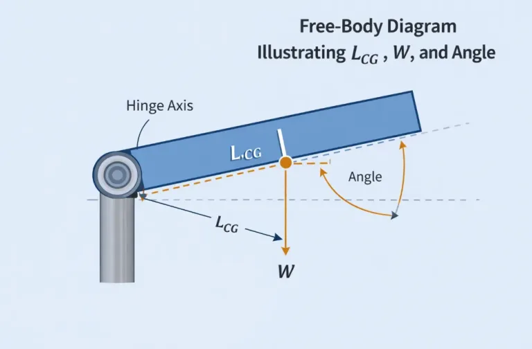
Gravity acts downward at the assembled center of gravity. The hinge system must transfer that vertical load into the frame, but it must also resist the moment created because the center of gravity sits away from the hinge axis. In a simplified rigid-door model, the upper and lower hinge regions develop opposing horizontal reactions. One region pulls away from its mounting surface while the other reacts in the opposite direction.
That is why the upper mounting area can show screw movement, plate bending, or weld distress even when a simple “door weight divided by hinge count” value looks modest. The hinge leaves, pins, fasteners, welds, reinforcement, and cabinet frame are consecutive parts of one load path. The weakest link may be outside the purchased hinge.
A useful preliminary equilibrium model
W = m × g
W is the assembled door weight force, m is mass, and g is gravitational acceleration.
M = W × e
M is the static moment about the hinge axis and e is the horizontal distance from that axis to the assembled center of gravity.
Fc ≈ M ÷ S
Fc is the ideal opposing reaction associated with the moment couple, and S is the effective distance between the upper and lower reaction zones.
For the complete hinge set, ΣVi = W. Fc represents the opposing reaction couple required to balance W × e; it is not W ÷ n and should not be added to the total vertical shear.
These are general statics relationships, not an HTAN product rating and not a complete hinge calculation. They assume a stable geometry and do not distribute vertical shear among three or more hinges. They also omit fastener-group eccentricity, hinge-leaf flexibility, contact clearances, frame distortion, dynamic loading, and manufacturing variation. Use them to expose the load path and screen a layout, then complete the structural review with the real assembly.
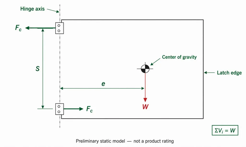
Hinge Spacing for Long Industrial Doors
In the ideal model, increasing the effective spacing S reduces the opposing reaction needed to resist the same moment. The word effective matters. Moving a hinge closer to the top edge does not help if that edge is a flexible flange with no reinforcement behind it. The layout gains useful spacing only when the upper and lower mounting zones can transfer load into a stable frame.
Edge distance, access for fasteners or welding, formed returns, gasket geometry, corner joints, and nearby cutouts can limit the usable locations. The largest geometric spacing is not always the strongest arrangement. A slightly smaller spacing tied into two frame crossmembers may outperform a wider arrangement attached to unsupported sheet.
Why a third hinge does not add capacity evenly
For several hinges to share load, their mounting points must deform compatibly. If the middle hinge axis is slightly offset, it may contact first and attract load, or remain partly unloaded until the door and frame deflect. A stiffer local mounting plate can attract more reaction than a flexible plate beside it. Pin clearance and leaf stiffness add another layer. The vertical shear therefore satisfies equilibrium as a total, but it should not be assigned as W ÷ n without a justified load-sharing model.
The third hinge can still be valuable. It can restrain the hinge-side edge between the end supports, limit local door bow, provide redundancy, or support a long section near a structural crossmember. Its position should follow the door and frame structure rather than a universal percentage of door height.
The Frame Decides Which Supports Work
A catalog hinge can be stronger than the panel that holds it. Thin sheet near a fastener group may dish outward, holes may elongate, a threaded insert may rotate, or a narrow flange may twist. A welded hinge can move the same problem into the heat-affected mounting zone, the edge of a reinforcement plate, or the frame joint that receives the reaction.
Review the mounting area as a structural joint. Door-side and frame-side stiffness both matter. Useful details include formed returns, hat sections, box sections, backing plates, doubler plates, welded brackets, insert spacing, and the distance from the hinge reaction to the nearest frame corner or crossmember. A broad, thick hinge leaf does not repair a load path that terminates in flexible sheet.
The drawing fits, but the frame still moves. Consider two layouts with the same door mass, hinge model, center spacing, and fasteners. Layout A connects each hinge to a closed frame section. Layout B uses the same hole pattern on an unsupported sheet flange. The purchased hardware is identical, yet Layout B can rotate locally and drop the latch edge. Increasing the hinge rating alone would not remove that structural compliance. This is an illustrative engineering scenario, not a customer project record or product test claim.
When this interface is welded, the hinge layout still has to be separated from the full welding specification. Weld size, length, sequence, base material, distortion control, and inspection belong in a controlled fabrication review. The present task is narrower: make sure the reaction enters a frame region designed to carry it.
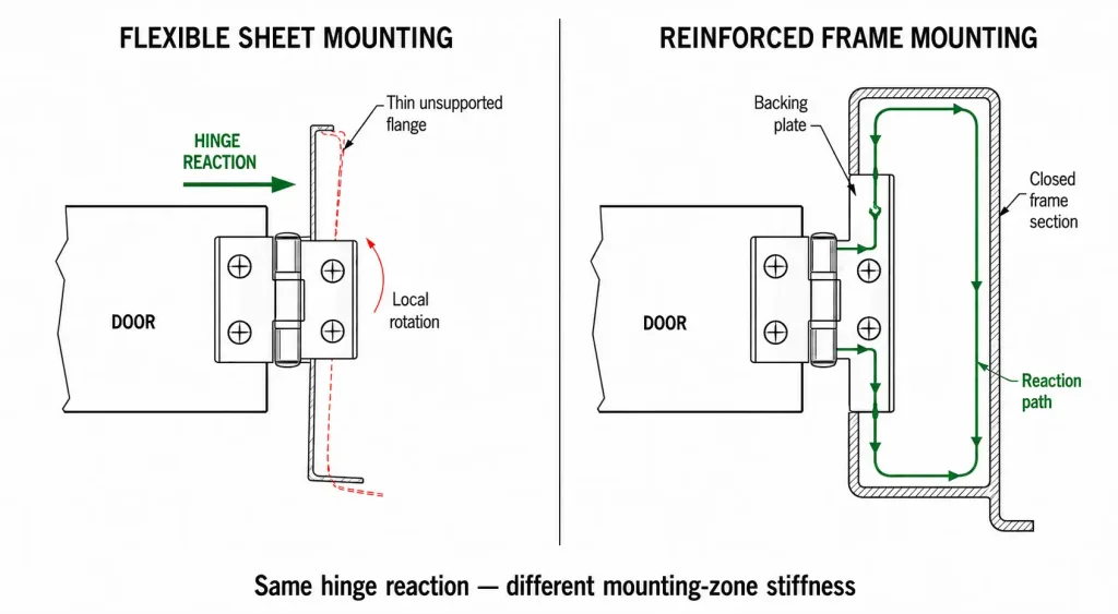
Mounting Joints Carry Combined Loads
The reaction begins at the pin axis, but the fasteners or welds usually sit on an offset mounting plane. That offset can bend the hinge leaf and introduce a local joint moment in addition to vertical shear and the upper-to-lower force couple. A wide leaf or a large fastener pattern may reduce local demand, but only when the leaf, attachment, backing structure, and parent material work together.
In a bolted joint, clamp load may resist movement through friction before the fastener shank bears against the hole. If the sheet slips, local bearing, tear-out, pull-through, insert rotation, and fastener tension can become relevant. The screws do not necessarily receive equal force: pattern geometry, edge distance, plate flexibility, preload, and manufacturing clearance all affect the group response. Specify the joint and substrate used for the supplier rating or sample test.
A welded joint follows a different local path through the hinge leaf, weld, heat-affected base material, reinforcement, and frame. This page does not select weld size, length, process, or inspection. It requires the designer to show where the calculated hinge reaction enters the frame and to confirm that fabrication distortion does not move the common axis. Exact bolted and welded joint capacity remains Engineering Review Required.
Two, Three, or More Discrete Hinges
Hinge count follows the structural model, not a spacing slogan. Two hinges create a clear upper and lower reaction pair, but each mounting zone must carry a larger share of the joint demand. Adding a middle hinge can support a long door edge, yet it also increases sensitivity to axis and mounting-surface variation. Four or more supports can be appropriate on a very long, flexible, or segmented structure, provided the manufacturing process can keep the hinge line straight.
| Layout | What it can accomplish | What can defeat it | Engineering action |
|---|---|---|---|
| Two discrete hinges | Establishes a simple upper/lower reaction pair and reduces compatibility variables. | High local demand at two mounting zones; unsupported door edge between them. | Calculate the preliminary moment couple and review both reinforced joints. |
| Three discrete hinges | Adds support near a crossmember or controls hinge-side edge movement. | Assuming one-third load per hinge; middle-axis offset; inconsistent local stiffness. | Choose the middle location from structure and validate installed load sharing. |
| Four or more discrete hinges | Supports a long or flexible hinge-side edge at several structural nodes. | Frame straightness, accumulated hole-position error, pin-axis mismatch, assembly binding. | Define a common axis datum and verify movement after final frame assembly. |
| Existing mounting pattern | May reduce retrofit work when the door and frame remain structurally sound. | Inherited hole damage, distorted sheet, weak inserts, or a pattern unrelated to current mass. | Inspect the old joint before treating the pattern as a design constraint. |
No row in this table approves a hinge count. The decision remains preliminary until the joint capacity, door response, and installation process are reviewed. If the project needs available discrete hinge constructions rather than a structural tutorial, continue to heavy-duty hinges for industrial doors after the door inputs are defined.
Alignment Changes Load Sharing
A spacing layout exists on paper. The installed hinge line exists after sheet forming, welding, coating, frame assembly, and fastener tightening. Every one of those operations can move an axis. If multiple hinge pins are not coaxial, the door may need to elastically deform before all hinges rotate. Opening force rises, one pivot wears faster, and the intended load distribution changes.
The drawing should establish a common hinge-axis datum or another measurable alignment method. Hole positions alone may not control the final pin centerline when leaves, pins, clearances, mounting faces, and weld distortion stack together. A fixture can help, but the fixture reference and the final cabinet geometry must agree.
This page does not diagnose binding, debris, pin wear, or fretting in the field. If the installed door already feels tight or shows uneven pivot wear, use the separate guide to multi-hinge axis alignment rather than adding another hinge to an uncorrected axis.
Full-Length Support Is a Reference Model
A full-length hinge and a set of discrete butt-style hinges attach the door edge differently. More attachment points can spread some local joint reactions and the long leaf can change edge stiffness. That does not guarantee uniform load at every fastener. The actual distribution still depends on leaf stiffness, fastener slip, frame straightness, door deformation, pin fit, and how the ends of the hinge line react to the moment couple.
Supply boundary: HTAN does not sell continuous or piano hinges. The distinction is retained only because engineers may begin with that comparison when investigating load distribution. This article’s product path is limited to discrete structures that HTAN actually supplies. The correct substitute is not “more individual hinges” by default; it is a discrete support layout tied into a frame that can carry the reactions.
An existing outdoor cabinet that already shows latch-side drop, gasket leakage, or frame distortion is a different task. Document hinge wear, mounting-hole condition, door flexibility, frame flatness, and latch position before changing the layout. Repair yielded or distorted structure first; a revised hinge arrangement should not be asked to conceal an unresolved frame failure.
Stops and Door-Mounted Equipment
The static open-door condition is only one load case. A rigid stop close to the hinge can introduce a short, severe load path when the door reaches its opening limit. A stop at the frame, a gas spring, a stay, a cable, or a nearby structure can also pull the door out of plane. None of those reactions is represented by M = W × e.
Door-mounted controls and windows deserve attention for another reason: they may move the center of gravity away from the hinge line and can make the door less stiff around cutouts. A late HMI addition can therefore increase the moment while weakening the panel region that distributes it. Recalculate the mass properties and inspect the door section whenever mounted equipment changes.
Transport vibration, wind, slam, impact, and seismic demand require project-specific load definitions. Do not copy a generic safety factor from another door. The equipment risk assessment, customer requirements, applicable machinery rules, and test plan must establish the credible load cases and acceptance margin.
The Latch Can Hide Hinge-Line Movement
When the door is closed, the latch or a lower frame contact may temporarily support the free edge. The door can appear level even though the hinge-side joints move when the latch is released. Treating that contact as a structural support is valid only when the equipment design intentionally defines it that way and the contact remains controlled through wear, temperature, gasket compression, and manufacturing variation.
Observe the door in both open and closed states. Measure latch-edge position before engagement, the force needed to pull the door into the latch, and any vertical movement as the latch releases. A rising closing force can indicate hinge-line movement, gasket change, frame distortion, or latch error; it is not proof of one cause by itself. The prototype must include the final latch and gasket so those reactions are not introduced only after the hinge layout has been approved.
Prototype Evidence at the Latch Edge
The latch-side corner is a useful observation point because small rotation at the hinge line becomes visible across the door width. It is not the only measurement. A door can return to the correct latch position while fastener holes are beginning to move, a backing plate is yielding, or opening force is increasing because the axes are fighting each other.
Test the representative door with its final mass, mounted equipment, gasket, latch, stops, and installation structure. If production frames are welded after hinge holes are established, the sample should represent that sequence. A rigid laboratory fixture can overstate performance when the production cabinet wall is the flexible part of the design.
| Evidence | What it can reveal | Record before and after testing | Acceptance source |
|---|---|---|---|
| Latch-edge position | Net rotation or deformation of the hinge-side system. | Reference location, door angle, load state, measurement method, and displacement. | Equipment fit, latch, gasket, and clearance requirement. |
| Opening and closing force | Binding, alignment change, or growing pivot friction. | Force application point, door angle, direction, speed, and instrument. | Operator or actuator requirement. |
| Mounting-zone condition | Hole movement, sheet dishing, insert rotation, weld distress, or plate-edge yielding. | Marked fastener positions, photographs, torque state where controlled, and deformation evidence. | Joint design and project inspection criteria. |
| Hinge-line straightness | Frame distortion or accumulated axis error after assembly and cycling. | Datum, measurement locations, door state, and tooling used. | Drawing tolerance and installed function. |
| Free play | Pin, bushing, knuckle, fastener, or mounting wear. | Load direction, measurement point, door angle, and repeatability. | Latch alignment, sealing, safety, and service requirement. |
Calculation, sample, and production approval are different statements. A statics model can justify a preliminary layout. A representative sample can show whether that layout works on one controlled assembly. Production approval still requires the drawing, fabrication process, inspection method, and allowed variation to reproduce the tested load path.
Put the Support Layout on the Drawing
A hinge count in a bill of materials does not control where the reactions enter the frame. Release the geometry and structural assumptions that made the arrangement acceptable. Unknown project values should remain To Be Confirmed rather than becoming copied dimensions or generic tolerances.
- Complete door dimensions, material sections, and assembled mass
- Center-of-gravity location relative to the installed hinge axis
- Hinge quantity, part reference, orientation, and center coordinates
- Effective upper-to-lower support spacing used in the preliminary model
- Door-side and frame-side mounting sections at every hinge location
- Backing plates, formed returns, brackets, inserts, fastener groups, and weld zones
- A common hinge-axis datum and the inspection method used after frame assembly
- Door-mounted equipment, gasket and latch interfaces, opening stops, and external restraints
- Static, dynamic, transport, wind, vibration, misuse, or other project load cases
- Prototype configuration, measurement locations, test sequence, and project-specific acceptance criteria
For machinery projects, the broader equipment context can be organized through industrial machinery hinge applications. Keep this page responsible for the long-door support layout; let the application page retain machine access, guarding, clearance, maintenance, and environment decisions.
Send the Door Layout, Not Just a Hinge Photo
For a discrete-hinge inquiry, provide the assembled door mass, door width and height, center-of-gravity location, proposed hinge coordinates, frame and door sections, reinforcement details, mounting method, opening stop, service frequency, and the required latch-edge or alignment acceptance. These inputs allow the inquiry to be matched to available heavy-duty, weld-on, lift-off, concealed, or other supplied hinge structures before a model or sample is discussed.
Submit the long-door hinge layoutQuestions Before Releasing the Layout
How far apart should hinges be on a long industrial door?
There is no universal spacing dimension. Start with the assembled door weight and center-of-gravity offset, estimate the moment about the hinge axis, and maximize the useful distance between upper and lower reaction zones that connect to structurally effective parts of the frame. Edge geometry, reinforcement, gasket clearance, installation access, and alignment tolerance can limit the usable spacing. Final spacing requires an engineering review of the actual door and frame.
Does adding a third hinge increase door load capacity?
Not by a fixed percentage. A third hinge can support a long hinge-side edge or connect the door to another frame crossmember, but its load share depends on axis alignment, pin and leaf clearances, local joint stiffness, and door and frame deformation. Do not calculate capacity by multiplying a two-hinge rating or by dividing the door weight equally among three hinges.
Why can the upper hinge mounting zone carry a high reaction?
The door’s center of gravity is offset from the hinge axis, creating a moment equal to door weight multiplied by that offset. The upper and lower support regions develop opposing reactions to resist the moment. The upper joint can therefore experience pull-away force and local bending in addition to its share of vertical shear. The exact reaction depends on geometry and structural stiffness.
Can a stronger hinge compensate for a flexible door frame?
No. A higher hinge rating does not automatically prevent thin sheet, an unsupported flange, a weak insert, a weld zone, or a flexible frame from deforming. The hinge, fasteners or welds, reinforcement, door section, and frame must form a continuous load path. If the mounting structure governs, reinforce or redesign that structure and validate the complete door.
How do butt hinges differ from continuous hinges in load distribution?
Discrete butt-style hinges introduce reactions at separated support zones. A full-length hinge uses a longer leaf and more attachment locations, which can spread some local joint demand and change edge stiffness. It does not guarantee uniform load at every fastener; the distribution still depends on the hinge, fasteners, door, frame, alignment, and mounting stiffness. HTAN does not sell continuous or piano hinges and uses this distinction only as a structural reference.
Defensible hinge spacing for long industrial doors requires the center-of-gravity moment, effective support distance, mounting-zone stiffness, common axis, and installed-door evidence to describe the same assembly. Until those elements agree, the hinge count remains a preliminary arrangement rather than production approval.

 English
  한국어
한국어  Русский
  Español
  Italiano
  Deutsch
  Français
  Português