

Stamped vs Die-Cast vs Machined Industrial Hinges: How to Choose for OEM Production
A stamped leaf, a die-cast body and a machined hinge can occupy nearly the same space on an assembly drawing. That does not make them interchangeable. Each route places cost, dimensional variation and production risk in a different part of the program. The cheapest sample can become the most expensive production choice once tooling, secondary machining, inspection and assembly are counted.
The practical question is not which process is “best.” It is which process creates the required hinge geometry with a stable, inspectable route at the intended production volume. Stamping starts with sheet and rewards geometry that can be cut and formed. Die casting earns its place when a three-dimensional body can integrate bosses, ribs, stops or pockets. Machining removes material to create controlled local features and remains flexible when quantity or geometry is unsettled.
Machining can be either the primary manufacturing route or a secondary operation. The distinction matters. A die-cast housing with a machined pivot bore is still a die-cast production architecture; a hinge cut entirely from billet follows a different cost and capability path.
Selection rule: Choose the primary route from the geometry, critical interfaces, expected volume and design stability. Then identify every feature that must be pierced, drilled, reamed, tapped, ground or inspected after the base shape is made.
The Geometry You Cannot Change
Begin with the hinge features that are fixed by the equipment, not with a supplier’s preferred machine. The mounting envelope, pivot location, door offset, opening path and adjacent components usually eliminate more options than annual quantity does.
A mostly flat hinge leaf with pierced holes, formed offsets and a rolled knuckle naturally fits sheet processing. A compact housing with internal cavities, supported bosses, ribs and an integrated stop may justify die casting. A low-volume hinge with thick sections, several datum-related bores or geometry that is still changing may begin as a machined part.
Do not classify the part by appearance alone. A thick-looking hinge can be assembled from formed plates. A cast-looking body may be machined from stock. The useful classification follows the process that creates the load-carrying base geometry.
| Hinge feature | Stamping starts well when | Die casting starts well when | Machining starts well when |
|---|---|---|---|
| Leaf or body form | Section is derived mainly from sheet thickness, bends and rolled edges | Body needs integrated three-dimensional mass, ribs, pockets or bosses | Part needs thick local sections, open tool access and flexible geometry |
| Pivot support | A rolled knuckle or attached barrel can carry the required load | The housing can support a molded pivot boss or bearing seat | Pivot bores and faces require direct control from machined datums |
| Mounting interface | Pierced or secondary-drilled holes suit a flat leaf | Raised pads, recessed seats or cast bosses reduce separate pieces | Counterbores, threads and mounting faces change frequently or need local precision |
| Mechanical stop | A formed tab or added stop is sufficient | A broad stop surface can be integrated into the body | Stop angle or contact geometry is still being tuned |
| Design maturity | Geometry is stable enough to commit forming tools | Three-dimensional geometry is stable enough to commit a die | Revisions are still likely or demand is limited |
Stamped Hinges: Sheet Geometry at Scale
Stamped industrial hinges begin with coil or sheet. Blanking and piercing establish the outline and holes; bending creates offsets or flanges; rolling forms the knuckle on many butt-style constructions. These operations may run in separate tools or in a progressive sequence, depending on volume, part size and process design.
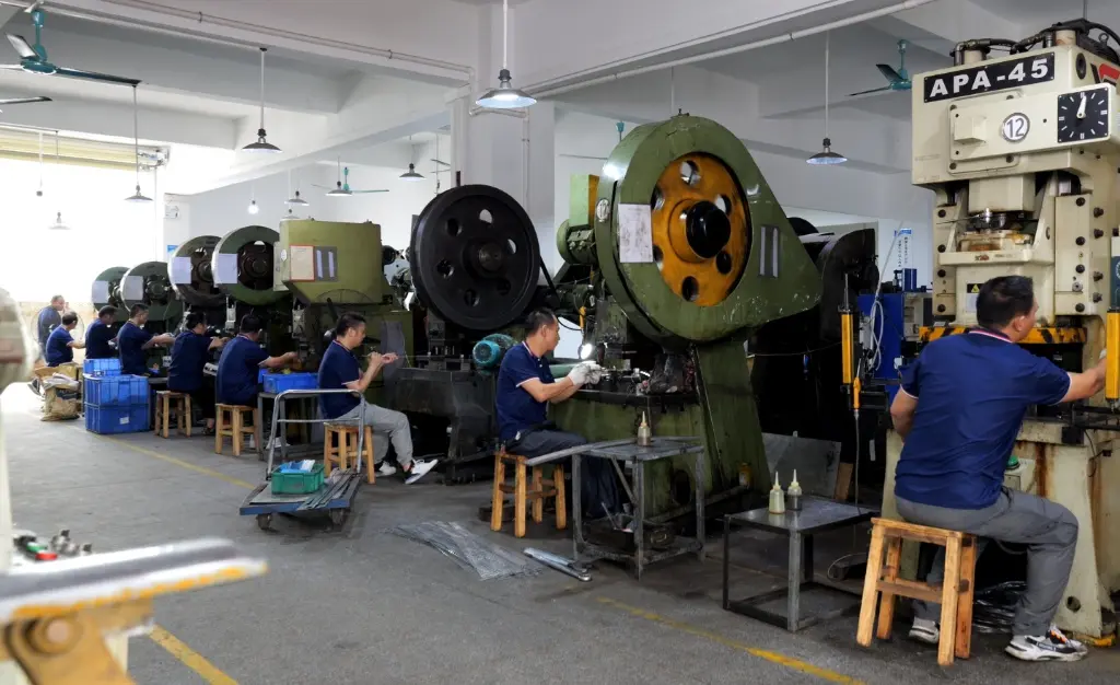
HTAN workshop record: The photo below shows our in-house sheet-metal stamping operation used for industrial hinges and related hardware. Actual press selection, tooling sequence and achievable tolerance are reviewed against the part size, material, forming depth and finished hinge requirements.
Where stamping is efficient
Stamping is a strong starting route when the hinge can retain a largely uniform sheet thickness and the functional shape comes from cuts, bends, embosses or rolled features. Once the tool and material feed are stable, the process can produce leaves quickly with repeatable outlines. Hole piercing, countersinking, coining and local embossing may also be incorporated where the design and tool permit.
The process favors designs that work with the sheet rather than fight it. Formed returns can add stiffness without increasing the full leaf thickness. Embosses can create local spacing or reinforcement. Separate pins, bushings, washers, nuts or brackets can provide features that would be awkward to form in one piece.
Variation does not stop at the blank
A pierced blank may meet its flat-state inspection and still shift after bending or knuckle rolling. Material thickness, grain direction, tool wear, springback, bend sequence and residual stress all influence the finished leaf. Holes located close to a bend can distort. A rolled barrel can move the pivot centerline relative to the mounting face. Burr direction may affect seating or assembly.
This is the hinge-specific trap: the mounting pattern and pivot axis are often created by different tool actions. A good flat blank does not prove that the assembled pin axis will sit correctly after forming. Inspection therefore needs to follow the finished state that controls installation and rotation, not only the convenient in-process state.
Die-Cast Hinges: Integrated Body Features
Die casting becomes attractive when the hinge body needs geometry in several directions: mounting bosses, ribs, pockets, bearing supports, covers, stops, recesses or cosmetic transitions. Those features can reduce a multi-piece stamped assembly to one body. Fewer loose pieces may simplify assembly, but the die now owns more of the product definition.
The die requires draft, a parting strategy, gates, overflows, ejection and controlled wall transitions. These are not supplier-side details that can be ignored until tooling. A rib that looks helpful in CAD may block ejection. A thick pivot support beside a thin cosmetic wall may create a difficult fill and solidification condition. A critical face may land across a parting line and need secondary machining.
Net shape is not automatically finished shape
Die casting can create detailed near-net geometry, but a hinge still may need trimming, drilling, tapping, reaming, facing or polishing. Pivot bores, bearing seats, datum pads and threads deserve particular attention. Their required position, surface condition and load determine whether the as-cast feature is acceptable or only a machining allowance.
Porosity is also a process reality, not a universal rejection. Its location and extent matter. Machining a bore or sealing face can expose subsurface discontinuities that were not visible on the as-cast surface. The drawing and control plan should identify which zones are function-critical and what evidence is appropriate for them.
Choosing zinc or aluminum after selecting die casting is a separate material decision. Density, wall strategy, thread behavior, temperature and finishing are compared in the zinc alloy vs aluminum alloy hinge guide.
Machined Hinges: Flexible Geometry, Paid Per Part
A fully machined hinge may start from plate, bar, billet, tube, an extrusion, a forging or another prepared form. Material is removed until the mounting faces, arms, bores, pockets and stops reach the released geometry. Dedicated casting or stamping dies may be unnecessary, which makes machining useful for low quantities, development builds and designs that are not ready for hard tooling.
Machining is especially useful when a small number of features drive the entire assembly: the pivot axis relative to the mounting face, a bearing seat, a controlled offset or a stop surface. Those relationships can be created from a planned datum structure and inspected after the same setups that produced them.
Flexibility is not free. Tool access, workholding, number of setups, material removal, cutter reach, thin-wall deflection, burr control and inspection time remain part of every piece. A feature that needs the part turned and re-established in a second fixture adds datum-transfer risk. Deep pockets and long slender tools can reduce stability. A thin machined leaf may distort after material is removed from one side.
“CNC machined” is therefore not a tolerance claim by itself. The machine, fixture, tool condition, program, setup sequence, thermal state and measurement method form one process chain. The supplier should connect the claimed capability to the actual hinge feature and production setup.

Tolerance Comes From the Process Chain
The drawing states the requirement. It does not make every process equally capable of meeting it. ASME Y14.5 provides a standardized language for expressing dimensions and geometric tolerances on drawings and model-based definitions. It does not select stamping, die casting or machining, and it does not prove that a supplier’s proposed process can hold the specified relationship.
For a hinge, separate features created directly by the primary process from features corrected later. A stamped mounting hole may be pierced before the leaf is bent. A die-cast bore may be cored and then reamed. A machined body may establish two coaxial bores in one setup or split them across fixtures. The finished tolerance depends on the complete sequence.
| Critical hinge relationship | Likely source of variation | Useful production evidence |
|---|---|---|
| Pivot axis to mounting face | Springback, die thermal condition, workholding or datum transfer | Finished-part measurement from the released assembly datums |
| Hole pattern after forming | Piercing position, bend distortion, coating buildup or secondary drilling | Post-form and post-finish dimensional results |
| Bore diameter and roundness | Core condition, porosity exposure, reaming, tool wear or clamping distortion | Defined bore measurement with the specified sampling plan |
| Leaf or mounting-pad flatness | Sheet residual stress, casting distortion, machining release or finish buildup | Contact-state or datum-based flatness inspection |
| Stop angle | Forming variation, cast stop location, machined contact position and assembly clearance | Functional angle measurement on the assembled hinge |
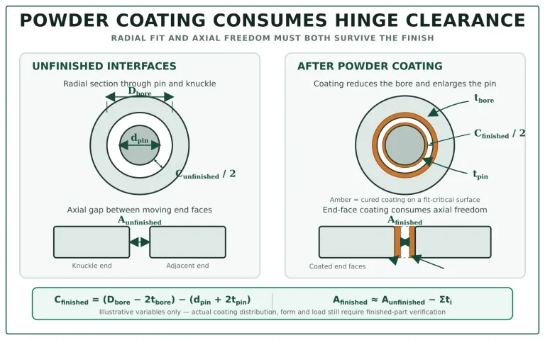
| Assembled end play | Knuckle stack, washer thickness, pin retention and coating | Finished assembly measurement under a defined direction and force |
The industrial hinge drawing checklist shows how approved features, datums, movement limits and inspection methods belong in the release package. Before that package is finalized, identify which critical relationships are created by the base process and which depend on a secondary operation.
Load Path Before Process Preference
No manufacturing route guarantees a stronger hinge. Strength comes from the material, section geometry, load direction, pivot support, fastener interface, stops and surrounding door structure. Manufacturing decides how that design is created and how consistently its critical features can be reproduced.
A stamped leaf can carry substantial load when its thickness, formed returns and mounting support create an effective path. A die-cast body can integrate ribs and broad bearing supports, yet a thin transition, poorly supported boss or concentrated stop load may govern. A machined part can retain thick sections and accurate interfaces, but unnecessary material does not correct an eccentric load path or weak mounting surface.
A common quotation error: three suppliers quote the same outside envelope, but one assumes a flat stamped leaf, one integrates the stop into a casting, and one machines the complete body. Their prices are not technically comparable until the load path, material, critical dimensions, finish and validation state are aligned.
Product approval must therefore follow the intended assembly. The process comparison can select a defensible direction, but it cannot create a load rating from geometry alone. Door mass, center of gravity, hinge quantity, support spacing, frame stiffness, external loads and cycle conditions still belong to the project.
Tooling, Volume and Design Stability
Annual quantity matters because tooling cost is distributed across usable production parts. It is not enough to ask which process has the lowest unit price at one forecast volume. The decision also depends on how stable the design is, how many revisions are likely, how long the program will run and which secondary operations remain on every piece.
A useful preliminary cost structure is:
Program cost = tooling + N × (part + secondary operations + inspection + assembly) + design-change exposure
For preliminary comparison, this cost structure exposes items that disappear when buyers compare only the line-item price. N should represent the expected number of acceptable parts, not merely the number ordered, because scrap, rework and process qualification can change the usable quantity.
Stamping and die casting can justify dedicated tooling when the design is stable and repeat demand uses the tool efficiently. Machining avoids some hard-tool commitment, but each part continues to carry machine time, workholding and inspection. A modification that is simple in a CNC program may require die rework, a replaceable insert or entirely new tooling in a formed or cast route.
There is no responsible universal break-even quantity. Part size, tool complexity, cavities, press operations, secondary machining, material utilization, quality requirements and supplier capacity all move the crossover. Ask each supplier to separate tooling, piece price and recurring secondary operations instead of hiding them inside one total.
Cost Comparison Example: A Cheap Part With an Expensive Assembly
Consider an OEM comparing three routes for a compact hinge with two mounting pads, a controlled pivot bore and an integrated opening stop. The stamped concept has the lowest quoted piece price, but it needs a welded stop, separate spacers and two post-form drilling operations. The die-cast concept integrates the stop and pads, although the pivot bore still needs machining. A fully machined sample is the fastest way to evaluate the opening geometry, but its cycle time remains in every production part.
If the team compares only the three piece prices, stamping appears to win. If it compares finished, inspected assemblies, the result may change. The correct choice depends on stable volume, tool commitment, assembly labor, tolerance evidence and whether the integrated casting can meet the actual load case.
Finish Changes the Production Sequence
Surface treatment sits after much of the geometry has been created, but it can change both dimensions and process order. A powder-coated stamped hinge may need protected pin, bore and end-face regions. A plated die casting may require finish-compatible alloy preparation and controlled coverage in recessed features. An anodized or passivated machined component may need critical bearing surfaces defined as coated, masked or finished afterward.
Post-finish machining can restore a bore or seating face, but it may also remove corrosion protection and create a new edge condition. Machining before finish protects the finished surface from tool marks but requires coating allowance and masking control. The route should state the required finished condition rather than leave the sequence to assumption.
Manufacturing-route selection does not define the complete corrosion system. Material, cleaning exposure, outdoor environment, galvanic contacts and finish acceptance still require their own review.
Hybrid Routes Are Normal
Many production hinges are not purely stamped, cast or machined. The base process creates economical mass; secondary operations create the critical interfaces.
- A stamped leaf may receive a machined pin, replaceable bushing, welded barrel or threaded insert.
- A die-cast housing may use machined bores, faced mounting pads and purchased friction components.
- A machined arm may be assembled to a stamped bracket to keep precision only where it is needed.
- A machined development sample may validate motion before a production casting or stamping tool is released.
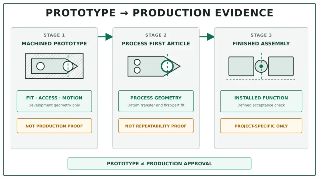
The last case needs discipline. A machined sample can prove envelope, motion path, assembly access and preliminary load behavior. It does not prove die fill, casting distortion, sheet springback, tool wear, formed-knuckle position or the surface condition of the production route. Prototype approval must state what the sample represents and what remains open.
The industrial hinge manufacturing process connects forming, machining, assembly and finishing into one production sequence. During quotation review, the stated process name may describe only the first operation, so the remaining operations must also be identified.
Manufacturing-Route Selection Matrix
The following matrix identifies a defensible starting route. When two rows point in different directions, the conflict usually indicates a need for a hybrid design, secondary operation or closer supplier review.
| Project condition | Defensible starting route | Why | Evidence needed next |
|---|---|---|---|
| Flat or formed leaves, stable geometry and sustained production demand | Stamping | Uses sheet efficiently and repeats cut-and-form geometry after tooling is established | Finished leaf, hole-pattern and pivot-axis capability after forming |
| Compact three-dimensional body with ribs, bosses, pockets or an integrated stop | Die casting | Consolidates features that would otherwise need several parts or operations | Die concept, critical-zone review and secondary-machining plan |
| Low quantity, frequent revisions or several tightly related local features | Machining | Avoids early hard-tool commitment and allows direct control from planned datums | Setup plan, fixture concept, cycle assumptions and dimensional results |
| High-volume flat leaf with one precision pivot feature | Stamped base plus machining | Keeps sheet efficiency while controlling the feature that governs motion | Datum transfer between forming and machining |
| Cast body with a bearing seat, precision bore or sealing pad | Die-cast base plus machining | Integrates the body while reserving critical interfaces for a controlled secondary process | Machining allowance, porosity-risk review and finished inspection method |
| Production process is undecided but motion geometry must be tested | Machined development sample | Supports rapid geometric learning without claiming production-process approval | Explicit prototype boundary and later samples from the intended production route |
| Existing catalog hinge nearly fits the project | Review the standard or modified-standard path first | A new manufacturing route may be unnecessary | Envelope, hole pattern, load, finish and modification limits |
When an existing catalog hinge nearly fits, compare the custom and standard hinge paths before authorizing new tooling. A standard or modified-standard part may avoid an unnecessary manufacturing program.
Prototype Evidence Before Tool Release
A supplier’s recommendation should arrive with more than a process label and piece price. The evidence must show how the intended route produces the hinge features that control fit, motion and load transfer.
- Process definition: primary route, material form, number of major operations and identified secondary machining.
- Tooling definition: dedicated die, forming tool, fixture or soft-tool status, including the revision represented by the sample.
- Critical-feature map: which operation creates the mounting faces, hole pattern, pivot bores, stop and assembled clearance.
- Dimensional evidence: results from the finished state, measured from the approved datums with the method stated.
- Material and finish identity: the actual condition represented by the sample, not a planned production substitution.
- Functional sample result: movement, stop behavior, mounting fit and application-specific load evidence under agreed conditions.
A first machined sample and a later die-cast sample may both be useful, but they approve different things. The development sample can close geometry questions. Production approval needs parts that include the intended tool, secondary operations, finish and assembly route.
Send a Manufacturing-Route Package
A useful review package includes the 2D drawing and 3D model, required material or permitted material family, finished-part condition, annual volume range, program duration, expected design changes, hinge assembly envelope, door or panel load inputs, opening angle, stop loads, mounting structure and the features that cannot move.
Mark the mounting datums, pivot axis, bearing or pin interfaces, hole pattern, stop surface and any appearance-critical surface. Identify which dimensions require recorded results. If a value is not yet available, label it as To Be Confirmed rather than replacing it with an assumed catalog tolerance.
Compare the Finished Production Routes
Send HTAN the hinge geometry, expected volume, material and finish direction, critical interfaces and available assembly data. The review can identify whether stamping, die casting, machining or a hybrid route is a reasonable starting point and what still needs sample evidence before release.
Stamped, Die-Cast and Machined Hinge FAQs
What is the main difference between stamped and die-cast industrial hinges?
Stamped hinges begin with sheet metal and obtain their geometry through cutting, piercing, bending, embossing and knuckle forming. Die-cast hinges begin with molten alloy injected into a die and can integrate three-dimensional bosses, ribs, pockets and stops. The correct route depends on the required geometry, critical interfaces, tooling commitment, volume and secondary operations—not on appearance alone.
Are machined industrial hinges stronger than stamped or die-cast hinges?
Not automatically. Strength depends on material, section geometry, pivot support, load direction, fastener interface, stops and the surrounding structure. Machining can retain thick sections and control local features, but a poorly arranged load path can still fail. Compare the complete designs under the same application conditions.
Which hinge manufacturing method has the lowest cost?
There is no universal lowest-cost route. Stamping or die casting may reduce recurring piece cost when geometry is stable and volume uses the tooling efficiently. Machining may cost less at low quantity or during frequent design changes because dedicated hard tooling can be avoided. Compare tooling, material, secondary operations, inspection, assembly, expected revisions and usable production quantity.
Can a CNC-machined prototype approve a later die-cast or stamped hinge?
It can approve selected questions such as envelope, motion path, installation access and preliminary assembly behavior. It cannot prove die fill, porosity exposure, casting distortion, sheet springback, formed-knuckle position, tool wear or production finish. Samples from the intended production route are still required for those conditions.
Do die-cast hinge bores and mounting holes need machining?
Some features may be usable as cast, while pivot bores, bearing seats, threads, datum pads or sealing faces may require drilling, reaming, tapping or facing. The decision depends on the selected alloy, tool design, feature size, location, tolerance, surface requirement and load. The drawing should distinguish as-cast features from finished features.
Which manufacturing route is better for tight hinge-axis control?
The best route is the one that creates the critical pivot features from a stable datum structure and demonstrates capability in the finished state. A stamped hinge may add post-form machining, a die-cast housing may ream its bores, and a machined hinge may require one controlled setup or a qualified datum transfer. The process name alone does not establish coaxiality or axis location.
Can one industrial hinge combine stamping, die casting and machining?
Yes. Hybrid process chains are common. A stamped leaf can use a machined pin or bushing; a die-cast body can have machined bores and faced mounting pads; a machined arm can be assembled to a formed bracket. The drawing and inspection plan should identify which operation controls each critical feature.
What should an OEM send for a hinge manufacturing quote?
Send the 2D drawing and 3D model, annual volume range, material and finish direction, mounting datums, pivot axis, critical dimensions, door or panel load inputs, opening angle, stop conditions, assembly envelope and required sample evidence. Mark unknown values as To Be Confirmed instead of allowing each supplier to make a different assumption.


 English
  한국어
한국어  Русский
  Español
  Italiano
  Deutsch
  Français
  Português