

Why Hinges Bind After Powder Coating: Clearance, Masking and Assembly Control
An assembled hinge can move freely at the bench and return from powder coating with a noticeably tighter pivot. That before-and-after change is the most useful starting point in a hinge binding after powder coating investigation. It narrows the problem, but it does not prove that “the coating is too thick” everywhere. The interference may be at the pin entrance, between adjacent knuckle ends, across a bridged barrel seam, or under a leaf that no longer seats as it did before finishing.
The repair is often deceptively simple: remove coating near the moving interface and the hinge turns again. The production fix is harder. It must identify which surface changed, which finished condition is acceptable, and how the next batch will preserve both corrosion protection and motion clearance without relying on hand scraping.
HTAN production note — scope and limits. A fully assembled carbon-steel butt hinge rotated normally before powder coating and became noticeably tighter after coating. The corrective action was to clear coating around the knuckle or pin area. No retained film-thickness reading, torque trace, cure record, sample quantity or formal report is available for that event. It is used here as a qualitative production observation, not as a product test claim, failure-rate statement or universal clearance recommendation.
The Coating Changed the Functional State
“The hinge passed inspection” is incomplete unless the inspection state is named. A loose, unfinished hinge and a cured, fully assembled hinge are different test articles. Powder coating adds material, creates transition edges at masking boundaries and exposes the assembly to a cure schedule. Any of those changes can alter a close-running pivot even when the stamped leaves, knuckles and pin were acceptable before finishing.
The first comparison should therefore be functional, not cosmetic. Record whether the hinge completed its required travel before coating, then repeat the same motion check after cure and cooling. Use the same direction, support condition and approximate operating rate. A hand check will not create a torque specification, but a controlled before-and-after comparison can show when the process introduced the change.
Do not start by polishing every visible surface. Preserve one representative stiff sample if possible. Scrape marks, coating lips and polished witness bands may be the only evidence that distinguishes local interference from a bent pin or distorted knuckle.
Coating Drag or Axis Error?
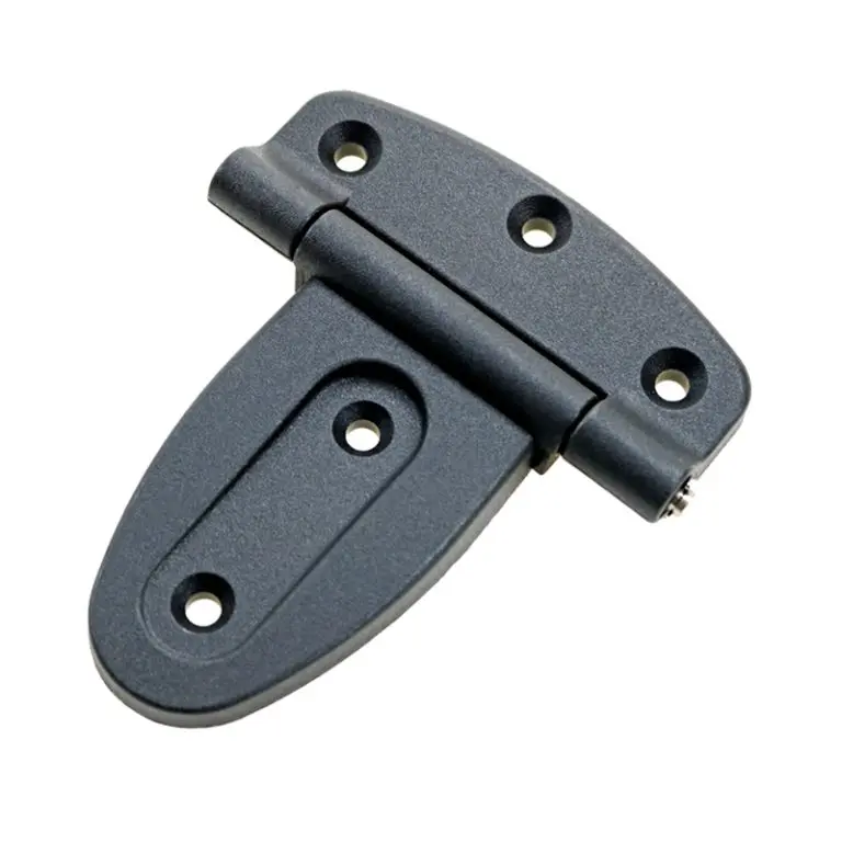
A hinge that becomes tight after coating may still have a geometric problem. The timing of the symptom is evidence, not a verdict. A formed leaf can move during handling, a pin can bend, and an installed door can force several otherwise free hinges onto incompatible axes. The motion signature helps decide which branch to inspect first.
| Observed behavior | More likely mechanism | Next evidence to inspect |
|---|---|---|
| Free before coating; uniformly tighter through most of the travel afterward | Coating intrusion at the pin/bore interface or continuous rubbing at a coated thrust surface | Witness band on the pin, coating inside the knuckle entrance, axial end-face contact |
| High breakaway force, then easier movement | Coating bridge or cured lip across a knuckle seam | Cracked film at the seam, loose flakes, a ridge at the first movement point |
| One or two tight angular positions | Uneven buildup, pin straightness error or knuckle distortion | Localized scrape marks and pin runout; compare the hinge before installation |
| Free as a loose hinge but tight after mounting | Leaf seating, fastener pull-down or incompatible installed axes | Mounting-face coating, panel flatness and the installed common axis |
| Free after local coating removal near the pivot | Coating interference is strongly indicated | Identify the exact removed surface before changing the complete finish process |
| Still tight after the suspected coating is cleared | Underlying geometry, contamination or damaged pin may remain | Disassemble if permitted; inspect pin, bore, knuckle alignment and debris |
If two or more installed hinges bind together while each loose hinge moves normally, move the investigation to the hinge-axis datum and coaxiality controls. Removing coating from a pivot will not correct unrelated hinge stations that do not share one axis.
Where Clearance Disappears
A butt hinge does not have one generic “clearance.” It has several local interfaces, and each reacts differently to coating. The pin rotates or slips relative to one or more knuckles. Adjacent knuckle ends need enough axial freedom to avoid clamping one another. The leaves must seat without a coating ridge tilting the barrel. The outer barrel surface may be cosmetic, while the pin diameter and bore are functional.
Identify the Actual Moving Pair
The component names alone do not show where sliding occurs. In one hinge, the pin remains stationary in selected knuckles while another knuckle rotates around it. In another, the pin turns with one member and moves relative to different bores. A retained pin, process pin, bushing or thrust washer can change the running pair again. Masking the visible end of a part called the “pin” is therefore not the same as protecting the surfaces that establish motion.
Before approving the finish instruction, mark the pin and leaves, hold the intended stationary member and cycle the hinge through a short controlled stroke. Observe which members move together and which surfaces move relative to one another. Confirm the result against the assembly drawing or a permitted disassembly when the mechanism is not visible. Define the no-coat boundary from that motion path; otherwise a drawing can leave the real running interface coated while unnecessarily exposing a cosmetic surface.
| Functional zone | What coating can change | Typical evidence | Control direction |
|---|---|---|---|
| Pin outside diameter | Increases the effective rotating diameter or creates a hard entry lip | Circumferential scrape band; difficult pin removal | Mask, use a process pin, or install the final pin after coating |
| Knuckle bore or bore entrance | Reduces available internal diameter, often unevenly near the opening | Powder residue or a polished crescent at the bore mouth | Protect the bore and define the mask depth/boundary |
| Ends between adjacent knuckles | Consumes axial gap or bridges the seam | Cracked film, flakes, bright end-face rubbing | Keep the movement gap open and control the transition edge |
| Thrust face or washer seat | Adds thickness to a surface carrying axial reaction | High drag under vertical load; worn coating ring | Define whether the face is coated, masked or fitted after coating |
| Leaf mounting face | Changes seating height or creates a local wedge | Loose hinge moves; mounted hinge binds | Control finished seating surfaces and installed inspection state |
| Fastener hole or slot | Reduces adjustment or shifts the leaf during tightening | Fastener scrapes coating; hinge locks at one side of a slot | Mask or size the finished feature for the required adjustment |
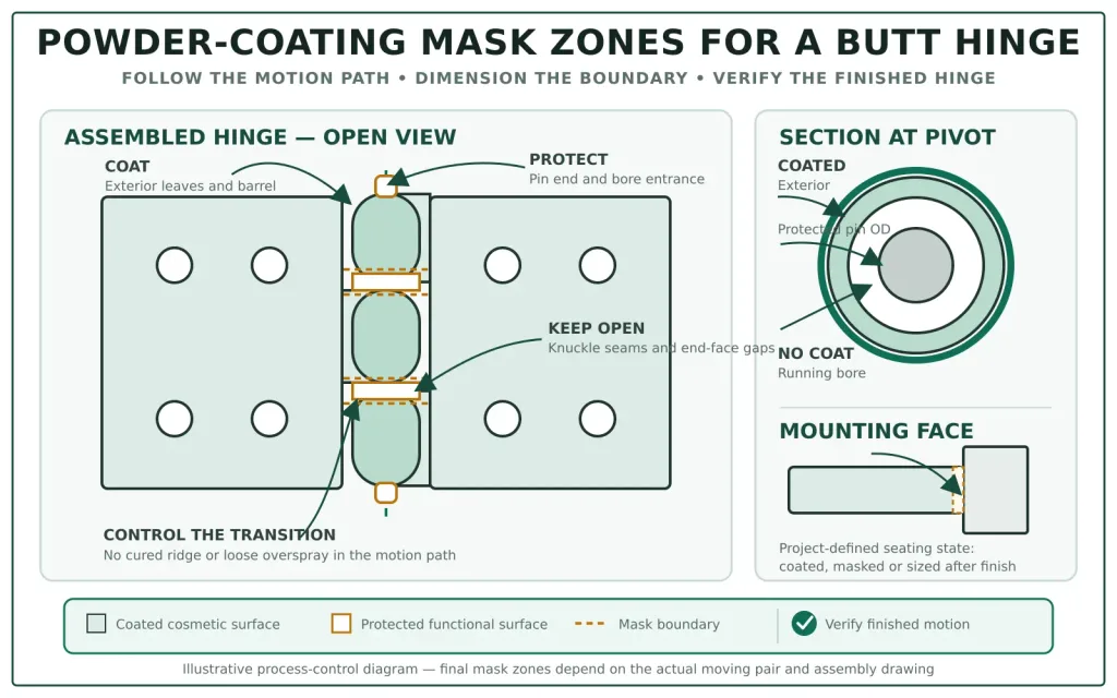
Coating on the exposed barrel is not automatically the problem. Trouble begins when the finish reaches a surface that establishes motion, axial freedom or seating. That is why “mask the hinge” is too vague for a work instruction. It does not identify which diameter, depth, face or transition line must remain controlled.
A Finished-Clearance Model
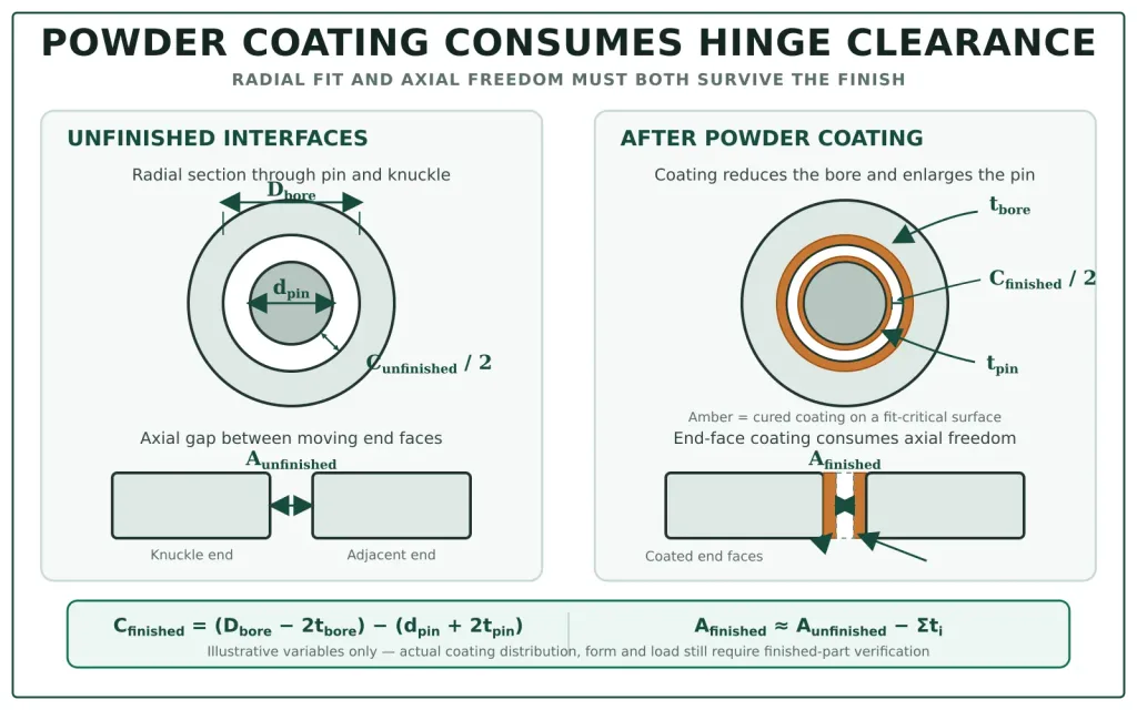
A simple dimensional model shows why small coating additions can matter at a close fit. Let Dbore be the unfinished knuckle bore, dpin the unfinished pin diameter, tbore the cured coating thickness on the internal bore surface and tpin the cured coating thickness on the pin surface.
Cfinished = (Dbore − 2tbore) − (dpin + 2tpin)
Preliminary diametral-clearance model; actual coating distribution and form error still require inspection.
Preliminary diametral-clearance model; actual coating distribution and form error still require inspection.
If the same nominal film builds on both the pin and the inside of the bore, the diametral clearance is reduced by four times that film value. Real powder distribution inside a narrow knuckle is rarely uniform, so the equation is a design envelope rather than a prediction of the cured shape. A thick lip at the bore entrance can bind even when the average internal film is much lower. A pin may also stay mostly uncoated while a bridged seam creates high breakaway force.
Check Axial Freedom Separately
Radial clearance does not describe the gap between adjacent knuckle ends, a washer and its seat, or a barrel and a retaining shoulder. Let Aunfinished be the available axial freedom before coating and let each ti represent cured film on a face that closes that specific gap.
Afinished ≈ Aunfinished − Σti
Include only the opposing coated faces that consume the defined axial gap.
Include only the opposing coated faces that consume the defined axial gap.
The number of contributing faces depends on the actual stack. Washers, shoulders, retainers and which knuckles move together must be identified before adding film terms. If resistance increases when the hinge is loaded toward one barrel end, then falls when the axial reaction is reversed or removed, inspect the thrust faces and knuckle-end gaps before enlarging the pin-to-bore fit. That behavior points to an axial load path; it does not by itself prove that radial clearance is acceptable.
Do not turn the equation into a universal allowance. The required finished clearance depends on hinge size, pin and bore form, load direction, desired free play, lubrication, temperature, coating chemistry and the operating-force requirement. Increasing clearance blindly can replace binding with rattle, door movement and accelerated wear.
Read the Witness Marks
Before removing coating, mark the hinge orientation and move it only enough to reproduce the symptom safely. Then inspect the pivot under direct light. The useful marks are usually directional. A continuous polished band suggests radial contact. Bright arcs at knuckle ends indicate axial rubbing. A fractured line across the seam indicates that the cured film bridged two members expected to move independently.
- Photograph the hinge before cleanup, including the complete barrel and both ends.
- Record whether the first movement is harder than later movement and whether resistance changes with angle.
- Check for flakes or powder dust at every knuckle junction.
- Inspect the pin entrance and any exposed pin section for a coating ring or transfer mark.
- Measure accessible finished diameters and film thickness at defined locations when suitable instruments are available.
- Remove coating from one suspected interface only, then repeat the same motion check.
Selective cleanup is diagnostically stronger than stripping the whole barrel. If several surfaces are changed at once, the hinge may move again but the root cause remains unknown. The next batch then receives a broad masking instruction that may expose unnecessary carbon-steel areas while still missing the actual interference point.
Masking the Functional Surfaces
A useful masking definition starts from function. The drawing or coating instruction should identify the moving diameter, bore depth, knuckle end face, seam width or seating area that must remain within the finished requirement. “Mask pin” does not state whether the pin may receive overspray at its end, whether the bore entrance must remain clean, or how far the mask boundary may move.
Masking also creates a corrosion tradeoff on carbon steel. Leaving an unnecessarily large bare barrel may preserve movement but remove the intended protective barrier. The objective is not maximum bare metal. It is the smallest controlled no-coat zone that protects the functional interface, paired with an appropriate material, lubricant, plating, seal or other project-approved protection where exposed steel would be unacceptable.
If the real decision is whether a coated carbon-steel hinge is suitable for the service environment at all, use the separate comparison of powder-coated versus stainless steel hinges. This page assumes powder coating has already been selected and asks whether the finished hinge can still move as required.
A mask boundary is a controlled feature. State where it begins, what may remain uncoated, whether edge feathering is acceptable, and how residual powder or adhesive will be removed. A clean-looking color boundary is not enough if a cured ridge sits in the motion path.
Assembly Before or After Coating?
Coating a complete hinge is attractive because the assembly reaches the coating line as one part and the exposed exterior can receive one consistent color. It also places the movement interface inside a process designed to deposit and cure material. Coating the components separately gives better access to functional surfaces, but it adds post-finish handling and can damage the appearance during pin installation.
| Process route | Functional advantage | Main risk | Evidence needed before release |
|---|---|---|---|
| Fully assembled, then powder coated | Simple part flow and consistent exterior appearance | Bridged seams, bore-entry buildup, trapped process residue and cure exposure of internal parts | Defined masking plus finished-hinge motion acceptance on representative production parts |
| Leaves coated separately; final pin installed afterward | Direct control of bores, pin and knuckle end faces | Finish damage or contamination during final assembly; added process step | Assembly tooling, pin-retention control and post-assembly appearance/function check |
| Assembled with a process or sacrificial pin | Maintains alignment while protecting the final pin | Process pin removal may damage coating or alter the bore | Defined pin size, removal method and final-pin fit after coating |
| Assembled and coated, followed by routine manual cleanup | Can contain a short-term production issue | Variable material removal, exposed steel and hidden rework cost | Rework instruction and verification; process correction required for continued production |
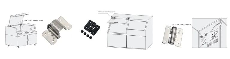
No route is universally correct. The released process must match the hinge architecture. A fixed-pin butt hinge, removable-pin hinge, bushed hinge and torque hinge do not expose the same components to coating and heat. Approval belongs to the exact material stack and assembly sequence, not to the word “powder coated” on a purchase order.
Heat-Sensitive Parts Inside the Barrel
Powder coating is also a thermal process. A plain all-steel butt hinge may tolerate the selected cure schedule while a hinge with a polymer bushing, elastomeric seal, retained lubricant, adhesive or preloaded friction element may not. Temperature at the part, time at temperature and the component supplier’s limits matter. Oven air temperature alone does not describe the thermal exposure of the hinge.
For a hinge containing nonmetallic or lubricated components, obtain the actual powder technical data sheet and compare its cure window with every internal material. If compatibility is unknown, do not infer it from a visually acceptable coating. A bushing can change dimensions, a lubricant can migrate or degrade, and an adhesive can lose retention without producing an obvious exterior defect.
This thermal branch should not be used to explain every stiff hinge. In the verified carbon-steel butt-hinge observation available for this article, no cure record or internal material record was retained. Local coating removal was the known corrective action, so the event supports an interference diagnosis more strongly than a heat-damage conclusion.
Cleanup Is Containment, Not Control
Clearing coating from the knuckle or pin area can restore movement and identify the affected zone. It is a reasonable containment action for a sample or segregated lot when the repair method, exposed surface and final function are reviewed. It is not automatically a production solution.
Uncontrolled scraping can score the pin, enlarge a bore entrance, remove corrosion protection and leave loose coating fragments inside the joint. Reaming after coating changes the finished geometry and exposes carbon steel. For continued production, convert the successful cleanup into one of three controlled changes: a defined masking boundary, a revised assembly sequence, or a validated finished-clearance change. The selected change should remove the interference without creating unacceptable free play.
Peeling, blistering or poor adhesion away from the moving interface is a different investigation. Those defects belong with base-metal condition, cleaning and hinge quality before surface treatment. Do not expand a pivot-clearance correction into a complete coating-quality diagnosis unless the evidence connects the two.
Drawing and Work-Instruction Callouts
The part drawing should define the finished function; the coating work instruction should define how the process protects it. When all requirements are buried in a general finish note, the hinge supplier, coating vendor and assembler may each assume another party owns the pivot interface.
- Inspection state: finished hinge, cooled and conditioned, with the production pin and specified lubricant or bushing installed.
- Coating system: approved powder designation or performance specification, color and supplier technical data sheet reference.
- Thickness locations: identify representative cosmetic measurement areas separately from fit-critical surfaces.
- No-coat zones: dimension the protected pin length, bore depth, end face, seam or seating surface from repeatable features.
- Mask transition: state whether ridges, loose edge film or overspray are permitted near the movement path.
- Assembly sequence: identify whether the final pin, bushing, washer and lubricant are installed before or after cure.
- Functional output: define opening angle, direction, rate, support condition and acceptable breakaway/running resistance for the project.
- Rework: state whether coating removal is allowed, which tools and surfaces are permitted, and how exposed carbon steel is protected.
If the finished hinge uses several separated pivot stations, the coating note cannot replace the assembly definition. Finished-state alignment and load-sharing requirements remain part of the multi-hinge door specification.
Finished-Hinge Acceptance
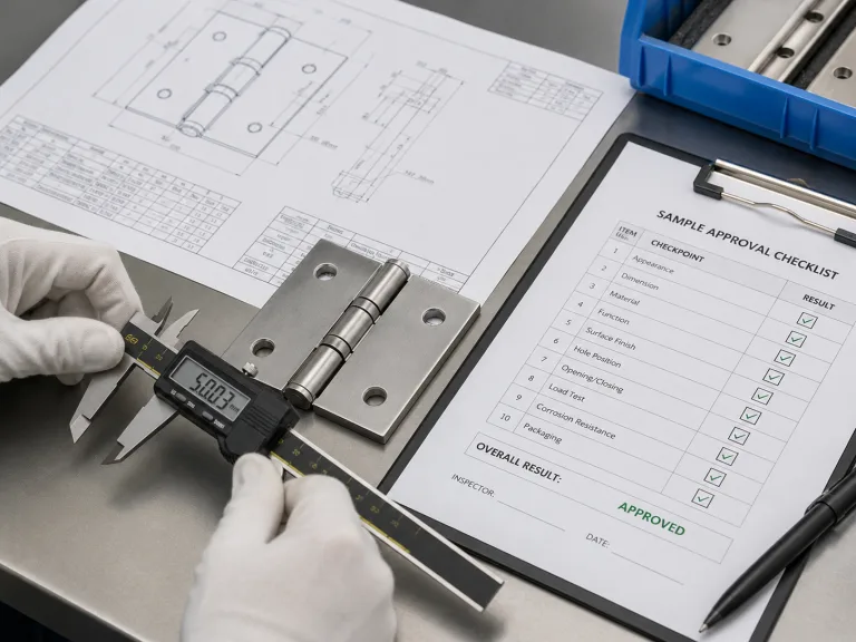
A visual coating inspection cannot accept pivot function. Conversely, one free swing does not prove coating quality or service durability. The release check should measure the output this page is responsible for: whether the finished hinge moves through the required angle with acceptable resistance and without coating damage at the controlled interfaces.
A film-thickness reading on the flat leaf—or on a process coupon—describes the coating where that reading was taken. It does not establish the film at a curved knuckle seam, recessed bore entrance or internal bore. Curvature, access and probe suitability can change what can be measured reliably. The inspection plan should name the measurement location and suitable instrument separately for cosmetic and fit-critical zones. Where direct measurement of the running interface is not practical, retain the finished-motion result and the witness-mark inspection as functional evidence instead of inferring the hidden film from a nearby flat surface.
- Condition the cured hinge to the temperature defined for inspection.
- Support it in the same orientation used for the approved baseline; do not add door load unless the requirement is for an installed assembly.
- Record the first breakaway separately from later movement. A seam bridge may fracture on the first stroke and disappear from a later average.
- Move through the complete required angle in both directions at the defined rate.
- Record breakaway and running force or torque when the project needs numerical acceptance. State the lever arm and measurement point if force is used.
- Inspect the pin entrance, knuckle ends and masking transitions again for cracking, transfer marks and loose flakes.
- Compare the result with the approved finished sample or project limit—not with an undefined expectation that the hinge should “feel smooth.”
No universal operating-force limit is stated here. A free-swinging access hinge, a gasket-loaded cabinet hinge and a friction hinge are intentionally different. The OEM must define the acceptable output for the actual hinge and assembly.
Where appearance and function conflict, record both results. A hinge may rotate after the coating seam cracks, but exposed steel, flaking finish or debris at the pivot can still make the sample unacceptable. Functional recovery alone does not approve the coating process.
Preventing hinge binding after powder coating comes down to preserving a defined finished motion interface. Diagnose the changed surface first, then control its masking, clearance, assembly sequence and finished operating resistance. That closes the process loop without turning one successful cleanup into an undocumented production method.
Share the Finished-Hinge Details
For a product or sample discussion, send the hinge type, base material, whether it is coated assembled or disassembled, the required opening angle, the coating specification, photos of the knuckle and a description of where resistance occurs. If available, include the pin diameter, bore size, masking drawing and before/after operating-force record. These inputs provide a practical basis for separating coating interference from an underlying hinge or mounting problem.
Hinge Binding After Powder Coating FAQ
Why did my hinge become stiff after powder coating?
Powder may have reduced pin-to-bore clearance, built up between adjacent knuckle ends, bridged a moving seam or changed how a coated leaf seats. Compare the loose hinge before and after coating, then inspect witness marks before removing material.
Can a fully assembled hinge be powder coated?
Yes, but only when the hinge architecture, masking, internal materials, cure exposure and finished-function check have been defined. A complete assembly should not be approved solely because its exterior coating looks uniform.
Should the hinge pin be masked before powder coating?
Mask the pin when coating on its diameter would reduce a controlled running fit or interfere with installation. The instruction should also address the bore entrance, knuckle end faces and mask transition; masking only the visible end of the pin may not protect the actual motion interface.
How much extra hinge clearance is needed for powder coating?
There is no universal allowance. Finished clearance depends on film at each opposing surface, pin and bore form, free-play limits, load, lubrication, temperature and required operating force. Calculate an initial stack, then verify representative finished parts.
Can I fix a powder-coated hinge by scraping coating from the knuckle?
Local removal can be a controlled containment action and may help identify the interference zone. It can also expose carbon steel, damage the pin or change the fit. Continued production needs a documented masking, clearance or assembly-process correction rather than undefined hand scraping.
Is the coating always the cause when a hinge binds after finishing?
No. The hinge may have been bent during handling, pulled out of line during mounting or affected by several incompatible pivot axes. If a loose finished hinge moves freely but the installed door binds, inspect mounting geometry and common-axis alignment.
Should butt-hinge components be coated before final assembly?
Separate coating can protect bores and pins more directly, but final assembly may damage the finish and requires controlled tooling. Coating the complete hinge can work with suitable masking and validation. Choose the route from the hinge design and finished acceptance requirement.
Can powder-coating cure heat affect hinge bushings or lubricant?
It can when the bushing, seal, lubricant, adhesive or friction element is not compatible with the actual part-temperature and time-at-temperature profile. Review the powder technical data sheet and each internal material limit before coating the assembled hinge.


 English
  한국어
한국어  Русский
  Español
  Italiano
  Deutsch
  Français
  Português