

How to Specify Industrial Hinges for Multi-Hinge Doors: Alignment, Load Sharing and Tolerance
Specifying industrial hinges for multi-hinge doors requires more than placing three identical part numbers on a drawing. One hinge may seat first, one mounting flange may be stiffer, and one pivot may sit outside the common axis after welding or coating. A defensible specification must control the complete assembly: the door condition, hinge coordinates, load-sharing basis, mounting structure, alignment tolerance and evidence required before the layout is released.
Specification rule: Treat the hinge set, door, frame, attachments and assembly process as one support system. Define what every hinge station is expected to do, what variation the installed door can accept and how that result will be measured. Do not approve the design by dividing door weight by hinge quantity.
Scope: This article addresses side-hinged industrial doors and access panels supported by two or more discrete hinges. It is a specification and supplier-review guide. Detailed load-path calculations, hinge-axis GD&T selection, field sag diagnosis and cycle-test methods remain with their dedicated technical pages.
Industrial Hinges for Multi-Hinge Doors
A multi-hinge arrangement should be released from one controlled definition of the finished door. The bill of materials may list three identical hinges, but the specification must also identify the frame, door construction, mounting joints, opening direction, latch, gasket, stops and any equipment attached to the moving panel. These items determine whether the hinge stations can share motion and load without forcing the door to twist.
Start by naming the assembly whose performance is being approved. Is it a bare door on a rigid development fixture, a painted enclosure with the production frame, or the complete machine with cables, window, lock and door-mounted controls? Those are different test articles. A hinge that rotates freely on a bench has not proved that three separated hinge stations will remain aligned after they are installed on a formed and welded cabinet.
The specification basis should connect four layers:
- System definition: the final moving mass, center of gravity, operating orientation and credible external loads.
- Support layout: hinge quantity, station coordinates, effective support spacing and mounting structure.
- Geometric control: the common pivot axis, mounting-interface variation and controlled assembly state.
- Functional acceptance: allowable sag, operating force, binding, latch-edge position, clearance and post-test change.
If one layer is missing, the supplier receives an incomplete problem. A catalog rating cannot reconstruct an unknown center of gravity. A precise hinge cannot straighten an uncontrolled frame flange. A smooth sample cannot establish production acceptance when the door-level measurement method has not been defined.
Configuration Baseline for the Released Assembly
A supplier cannot review a moving target. The specification should name one configuration baseline: the door and frame revisions, hinge set, finish condition, mounted equipment, latch, gasket, stops and any cable or stay that affects motion. Mass, center of gravity and acceptance results must be traceable to that same baseline. A value copied from an earlier panel revision should not remain in the release package after a window, HMI or inner liner changes.
The baseline is not a generic project-stage table. It is the evidence map for this door. Each controlled input needs a source, revision and re-review trigger. The supplier does not need every proprietary machine detail, but it does need the interfaces and load cases that affect the proposed hinge. Quality needs to know which finished state it will inspect.
| Baseline record | Controlled source | Information issued for hinge review | Re-review trigger |
|---|---|---|---|
| Door and frame configuration | OEM assembly drawing and bill of material revision | Dimensions, sections, finished state and functional interfaces | Material, section, cutout, reinforcement or finish change |
| Mass properties | Approved mass roll-up or measured assembly record | Final mass and center-of-gravity coordinates from the installed pivot axis | Added or relocated door-mounted equipment |
| Hinge set | Controlled hinge drawing and OEM part reference | Quantity, revision, orientation and station assignment | Model, material, pin/bushing or mounting-interface change |
| Load schedule | Project calculation or controlled requirements document | Operating orientation plus applicable static, stop, transport or external cases | Use condition, opening limit, restraint or risk requirement change |
| Production state | Assembly drawing and work instruction | Welded, coated, adjusted and finally secured condition used for acceptance | Fixture, welding, coating or tightening-process change |
| Functional limits | Equipment requirement and validation plan | Door position, operating force, binding, free play, latch and seal limits | Latch, gasket, operator or actuator requirement change |
A changed baseline does not automatically invalidate the hinge, but it does require a documented disposition. The responsible engineer should record whether the change is covered by the existing analysis and sample evidence, needs a limited recheck or requires a new approval. Silence is not a disposition.
Put Hinge Stations on the Assembly Drawing
The assembly drawing should show hinge quantity, controlled part reference, handing or orientation, station coordinates and the hinge feature used for those coordinates. A center dimension is ambiguous when the supplier drawing references a leaf edge, mounting pattern or knuckle end. Use one declared reference convention across the hinge set and show the effective upper-to-lower support spacing used by the approved load model.
Do not release “three hinges equally spaced” as the complete requirement. The note does not identify the station datum, mounting section, local reinforcement or allowable relocation. If a station must align with a crossmember or avoid a cutout, identify that structural relationship. If a slot permits adjustment, show its direction and keep the final locked position under the assembly requirement.
A hinge count in the bill of materials does not approve the layout. The drawing or referenced specification must connect every station to a usable mounting zone and to the common-axis requirement. Product-specific removal clearance, concealed motion envelopes or weld access belong on the applicable interface drawing rather than in a generic quantity note.
No universal count: the specification should not state that a door of a certain weight always needs two, three or four hinges. Count depends on the complete geometry, support stiffness, hinge construction, load cases and acceptable door response. A proposed count remains preliminary until the complete assembly is reviewed.
Write the Load-Sharing Assumption
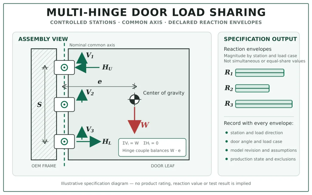
Static equilibrium requires the hinge set and any intentionally modeled latch, stop or contact point to balance the applied forces and moments. It does not prove that three hinges carry one-third of the vertical load each. Real load sharing depends on pin clearance, leaf stiffness, mounting-surface compliance, fastener slip, station alignment and the order in which the parts make contact. A small change in one station can cause it to attract load early or remain lightly loaded until the door deflects.
The specification should state the approved analysis basis instead of hiding it. If exact station reactions are not defensible, issue a conservative reaction envelope rather than an equal-share claim. For each envelope, identify the station or station group, force and moment directions, door orientation, operating or exceptional load case, production state and exclusions. A supplier can then compare the hinge and its mounting joint with a controlled demand instead of reconstructing the door model from a mass value.
| Specification field | Acceptable controlled entry | Not acceptable | Evidence reference |
|---|---|---|---|
| Model basis | Calculation or model document number, revision and responsible owner | “Based on engineering judgment” with no traceable record | Released calculation, model report or approved test plan |
| Station demand | Force and moment envelope by hinge station or justified station group | Door weight divided by hinge count | Reaction schedule attached to the assembly release |
| Directions and cases | Named coordinate system, door angle and applicable operating, stop, transport or external case | One scalar “hinge load” without direction or lever arm | Load-case table and door orientation drawing |
| Assumptions | Modeled contacts, clearances, support stiffness and any deliberately inactive hinge station | Implicit equal contact at every station | Assumption register and sensitivity review |
| Verification | Representative assembly method and the measurements compared with the model | Unidentified sample video or one smooth opening | Build record, instrumentation record and signed disposition |
The separate guide to hinge spacing and load distribution on long industrial doors owns the detailed weight, center-of-gravity moment, effective support spacing and frame-stiffness derivation. This specification page starts after that engineering decision: reference the approved model revision and transfer its station reactions, assumptions, exclusions and verification need into the controlled release.
Installed Common-Axis Requirement
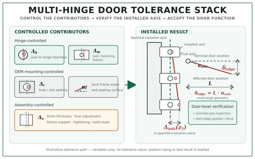
Multiple hinges can rotate freely only when their installed pivot features accept one functional axis within the door’s permissible error. Mounting-hole position alone does not guarantee that result because leaf clearance, mounting-plane tilt, knuckle clearance, welding, coating and final tightening can all move the installed axis.
The door-level specification should identify the shared assembly datums, the pivot feature or functional gage that represents each station, the evaluated axis length and the production state in which the relationship applies. The hinge supplier owns the pivot-axis relationship to the supplied hinge interface. The OEM owns the door-side and frame-side interfaces. The assembly process owns how adjustment and clearances are consumed. The released documents must connect those three responsibilities; the note “align hinges” does not.
Use the detailed guide to hinge axis datums and coaxiality when selecting datum features, position or runout controls, material-boundary modifiers and the inspection method. This page requires the common-axis result but does not duplicate that GD&T decision.
Drawing-standard boundary: ASME Y14.5 establishes symbols, rules and practices for stating and interpreting dimensional and geometric requirements. It does not prescribe a universal hinge-axis tolerance, decide which production assembly state governs or prove that the door will operate under load. Those remain project-specific engineering decisions.
Mounting Interface and Tolerance Schedule
Each hinge station needs a controlled mounting-interface definition. A generic hinge detail is insufficient when the upper station lands on a crossmember, the middle station lands on formed sheet and the lower station includes a backing plate. The schedule should identify the door-side and frame-side substrate, reinforcement, joint, functional seating area, finish condition and available adjustment for every station.
Reference the actual section that receives each hinge. Include material and thickness, formed returns, reinforcement boundaries, insert type, fastener pattern or controlled weld region, and distance to the structural feature that closes the reaction path. If two stations are intentionally different, do not label one section “typical” unless the controlled documents clearly preserve the difference.
Tolerance should be allocated backward from completed-door function. Begin with the permitted latch-edge displacement, operating-force change, seal variation or interference margin. Then assign portions to hinge internal geometry, axis-to-interface relationship, mounting features, local seating surfaces, fabrication and finish, assembly adjustment and elastic response. Keep manufacturing variation separate from in-service deformation so inspection does not confuse a dimensional nonconformance with a loaded structural response.
| Interface requirement | OEM drawing responsibility | Supplier return | Acceptance record |
|---|---|---|---|
| Axis to hinge interface | Identify the supplied hinge revision and the assembly feature that receives it | Controlled axis-to-mounting dimensions, datums and inspection state | Supplier dimensional report or certificate tied to revision |
| Mounting pattern | Basic coordinates, hole or slot type, locating intent and final locked position | Required hole pattern, hardware access and installation limitations | Door/frame feature inspection plus assembled position check |
| Functional seating area | Local surface extent, orientation, finish and permitted condition before clamping | Minimum supported leaf area and any flatness or seating dependency | Local surface check before assembly and witness after tightening |
| Substrate and reinforcement | Material, thickness, formed section, backing, insert, fastener or controlled weld reference | Substrate and joint conditions behind any quoted rating or sample result | Material traceability and section/joint inspection |
| Adjustment and clearance | Allowed direction, range, alignment method and secured production state | Hinge internal clearance and prohibited clamping or adjustment conditions | Work-instruction record and final common-axis check |
| Door-level tolerance allocation | Functional limit, contributor allocation and inspection ownership | Capability for the hinge-controlled contributors | Completed-door position, force, free-play and binding results |
Bolted and welded interfaces require different release evidence. A bolted joint should identify fastener and insert, hole type, controlled tightening condition and substrate. A welded bracket should reference the approved fabrication drawing and the finished inspection state; weld design, sequence and inspection remain within the OEM’s welding review. A hinge supplier should not be asked to approve an unseen parent structure from hinge geometry alone.
Every part passes; the middle hinge still fights the door
Consider a three-hinge enclosure door. Every hinge and every frame hole passes its local drawing, but the middle flange is slightly rotated and clearance lets that hinge lock toward the latch side. The upper and lower pins define one line while the middle pin sits outside it. Opening force rises because the door must flex before all three pivots rotate. The missing control is not another isolated hole tolerance; it is the installed common-axis requirement and completed-door operating-force acceptance.
This is an illustrative engineering scenario, not a customer project record or product test claim.
Production State, Deviations and Change Control
A requirement measured on an unfinished frame may not represent the completed enclosure. Welding can pull separated stations out of line. Powder coating can change leaf seating or consume a close fit. Gasket installation can preload the closed door. Tightening one hinge fully before the others can lock the assembly into a different position from a fixture-aligned sequence.
State the production condition for every critical measurement. Useful states include the fabricated frame before finish, finished frame before door installation, hinge set loosely assembled in the alignment fixture, fasteners tightened to the controlled condition and completed door with latch and gasket installed. Not every state needs an acceptance test. The specification should identify the state that represents the released product and any earlier process check needed to reach it.
If slots or clearance holes provide adjustment, describe the alignment method rather than treating adjustment as unlimited tolerance. Identify the reference shaft, laser, fixture, measured centerline or door-function check used before final tightening. Record whether the door is supported during alignment. A door aligned while its free edge is lifted can drop as soon as the temporary support is removed.
Replacement requirements deserve a separate note when interchangeability is important. A production process that hand-aligns every hinge may build a smooth new door but may not permit a field replacement hinge to return to the same axis. Decide whether service interchangeability comes from controlled locating features, a repeatable field adjustment or replacement of a matched bracket/hinge assembly.
An approved sample is valid only for its recorded configuration baseline. A hinge revision, frame section, coating system, weld fixture, hole or slot pattern, tightening sequence, latch, gasket or door-mounted equipment change requires a documented engineering disposition. The disposition should state whether existing evidence still covers the change, which limited checks must be repeated or whether a new representative assembly approval is required.
A supplier deviation request should identify the affected drawing or specification requirement, the reason for deviation, dimensional and functional evidence, affected quantity or time period, traceability method and approval authority. “Fit at assembly” is not an acceptable permanent disposition when the deviation can alter the common axis, station reaction, joint seating or service interchangeability.
Acceptance Evidence and Handoff
Component inspection cannot replace a functional check of the completed door. The acceptance plan should identify the controlled document and revision, configuration baseline, measurement owner, pass/fail authority and retained record. Outcomes may include latch-edge position, operating force, freedom from binding, reveal or seal consistency, free play and mounting-zone movement. Each limit needs a measurement state, reference point, direction and source in the equipment requirement.
Measure the door at defined angles because one value at the closed position can hide a problem. The latch may lift the free edge into place, and gasket compression can mask hinge-line movement. An alignment error may create maximum resistance at an intermediate angle rather than at either endpoint. For operating force, define where the force is applied, direction, opening versus closing, speed, temperature and whether the latch or seal is engaged.
| Acceptance evidence | Measurement definition | What a change can indicate | Acceptance source |
|---|---|---|---|
| Latch-edge position | Fixed frame datum, door angle, load state and vertical/horizontal direction | Net hinge-line rotation, structural deformation or free play | Latch engagement, clearance or seal requirement |
| Opening and closing force | Application point, direction, speed, angle range, temperature and interface state | Binding, friction change, seal preload or axis incompatibility | Operator, actuator or equipment requirement |
| Common-axis verification | Declared datum scheme, production state and inspection method | Station offset or tilt after fabrication and assembly | Assembly drawing and axis-control requirement |
| Mounting-zone movement | Witness marks, displacement points and load direction | Fastener slip, insert movement, sheet dishing or weld distress | Joint design and project inspection limit |
| Free play | Applied load, measurement point, door angle and repeatability | Pin, bushing, knuckle, fastener or mounting-interface clearance | Latch, sealing, positioning and service requirement |
| Post-test change | Same method and conditions as the approved baseline | Wear, settling, loss of preload or permanent deformation | Project-specific durability plan |
A cycle count alone is not an acceptance criterion. The project must define the load, motion angle, speed, dwell, environment, inspection intervals and failure limits associated with that count. Use the separate industrial hinge cycle testing protocol when developing the durability method. The multi-hinge specification should reference the approved test document and identify which door-level measurements are compared with baseline.
If the sample binds, do not immediately enlarge the alignment tolerance. First identify whether the resistance comes from pivot-axis error, leaf distortion, gasket compression, latch preload, contamination, stop contact or cable routing. A larger tolerance may reduce inspection rejection while leaving the actual assembly conflict untouched.
Supplier Return Package
The supplier should receive enough assembly information to understand the load and interfaces, but responsibility must remain clear. The OEM owns the complete door geometry, frame structure, equipment loads and functional acceptance. The supplier return package should close the product-specific questions without implying approval of the complete door.
Request the controlled hinge drawing and revision; pivot-axis relationship to functional mounting interfaces; material, finish and pin or bushing construction; mounting pattern and installation conditions; inspection capability for controlled dimensions; and any prohibited orientation, adjustment or clamping condition. If a rating or test result is provided, the return should identify load direction, lever arm, mounting substrate, hinge quantity, test state, duration or cycle definition and failure criterion. “Supports 100 kg” is not sufficiently defined for a multi-hinge door.
Sample evidence should identify the exact hinge revision, sample serial or lot traceability, quantity, door and frame construction, assembly sequence, load state, measurement method and approved deviations. A video of smooth motion can support review, but it does not replace dimensional records or before-and-after measurements. Photographs are most useful when they show the hinge stations, mounting reinforcement, latch-edge reference and witness marks—not only a close-up of the hardware.
Once the support basis is established, available heavy-duty hinge models can be reviewed against the actual mounting and load conditions. Product browsing should follow the specification inputs; it should not be used to invent them.
Release Package for a Multi-Hinge Door
The release package should let engineering, purchasing, the hinge supplier, fabrication and quality review the same assembly. Keep it short enough to use, but do not hide the conditions that made the layout acceptable.
- Identify the approved assembly. State the door and frame revision, finished condition, opening orientation and installed interfaces.
- Record final mass properties. Provide assembled mass and center-of-gravity location from the installed hinge axis.
- Dimension the support layout. Show hinge quantity, part reference, orientation, station coordinates and effective upper-to-lower support spacing.
- Declare the load-sharing basis. Reference the calculation, conservative station envelope, model or representative test used; do not use door weight divided by hinge count.
- Define the common axis. Identify the shared assembly datums, axis-defining features, production state and inspection method.
- Release the mounting structure. Include sections, reinforcement, fasteners or controlled weld interfaces at every hinge station.
- Control the tolerance chain. Allocate hinge, mounting, fabrication, finish and assembly contributors from the door-level functional limit.
- State the assembly method. Define any fixture, support, adjustment and tightening condition needed to reproduce alignment.
- Set functional acceptance. Give measurable limits for door position, operating force, binding, free play, seal or latch behavior and post-test change where applicable.
- Retain supplier evidence. Archive the hinge drawing revision, rating basis, sample configuration, inspection records and approved deviations.
If a value remains unknown, mark it as project-specific and assign a concrete next action. Do not copy a tolerance, hinge spacing or capacity statement from another door simply because its overall size looks similar. The released multi-hinge door specification should describe the actual load path and the actual production state that quality will inspect.
MULTI-HINGE DOOR SPECIFICATION NOTE PATTERN — PROJECT-SPECIFIC
1. HINGE QUANTITY, ORIENTATION AND STATION COORDINATES SHALL FOLLOW [ASSEMBLY DRAWING / REVISION].
2. THE INSTALLED PIVOT FEATURES SHALL MEET THE COMMON-AXIS REQUIREMENT RELATIVE TO [ASSEMBLY DATUMS] IN THE [DEFINED PRODUCTION STATE].
3. LOAD REVIEW SHALL USE THE FINAL DOOR MASS, CENTER OF GRAVITY, OPERATING ORIENTATION AND [DEFINED EXTERNAL LOAD CASES].
4. INDIVIDUAL HINGE LOAD SHALL NOT BE ASSUMED EQUAL UNLESS SUPPORTED BY [CONTROLLED MODEL OR TEST].
5. DOOR-SIDE AND FRAME-SIDE MOUNTING STRUCTURE SHALL FOLLOW [CONTROLLED SECTIONS / JOINT SPECIFICATION].
6. ALIGNMENT ADJUSTMENT AND FINAL FASTENER OR WELD CONDITION SHALL FOLLOW [WORK INSTRUCTION / FIXTURE DEFINITION].
7. COMPLETED-DOOR ACCEPTANCE SHALL INCLUDE [POSITION / FORCE / BINDING / FREE-PLAY / SEAL OR LATCH LIMITS] AT [DEFINED ANGLES AND LOAD STATES].
1. HINGE QUANTITY, ORIENTATION AND STATION COORDINATES SHALL FOLLOW [ASSEMBLY DRAWING / REVISION].
2. THE INSTALLED PIVOT FEATURES SHALL MEET THE COMMON-AXIS REQUIREMENT RELATIVE TO [ASSEMBLY DATUMS] IN THE [DEFINED PRODUCTION STATE].
3. LOAD REVIEW SHALL USE THE FINAL DOOR MASS, CENTER OF GRAVITY, OPERATING ORIENTATION AND [DEFINED EXTERNAL LOAD CASES].
4. INDIVIDUAL HINGE LOAD SHALL NOT BE ASSUMED EQUAL UNLESS SUPPORTED BY [CONTROLLED MODEL OR TEST].
5. DOOR-SIDE AND FRAME-SIDE MOUNTING STRUCTURE SHALL FOLLOW [CONTROLLED SECTIONS / JOINT SPECIFICATION].
6. ALIGNMENT ADJUSTMENT AND FINAL FASTENER OR WELD CONDITION SHALL FOLLOW [WORK INSTRUCTION / FIXTURE DEFINITION].
7. COMPLETED-DOOR ACCEPTANCE SHALL INCLUDE [POSITION / FORCE / BINDING / FREE-PLAY / SEAL OR LATCH LIMITS] AT [DEFINED ANGLES AND LOAD STATES].
This note pattern is not a substitute for geometric controls, structural calculations or the referenced acceptance documents. Its purpose is to keep the key relationships visible on the assembly release instead of scattering them across an email chain.
Multi-Hinge Door Specification FAQ
What should a multi-hinge door specification include?
It should identify the approved door and frame configuration, final mass and center of gravity, hinge quantity and station coordinates, declared load-sharing basis, installed common-axis requirement, mounting-interface details, production state, functional acceptance criteria and the supplier evidence required for release.
How should load sharing be specified when exact hinge reactions are unknown?
Do not replace missing reactions with door weight divided by hinge count. Reference the approved preliminary model, state a conservative station reaction envelope and load direction, list the assumptions and exclusions, and require representative assembly evidence when stiffness and clearance make the distribution uncertain.
What alignment tolerance should be used for a multi-hinge door?
Use a project-specific value derived from door function, not a universal number. The acceptable common-axis error depends on hinge spacing, internal clearances, latch-edge distance, seal and latch requirements, mounting stiffness, operating-force limit and the complete manufacturing tolerance chain.
Should hinge alignment be inspected before or after coating?
The released product should be accepted in the finished production state defined by the OEM. An earlier pre-coating check may be useful for process control, but it cannot replace the finished-state requirement when coating changes seating, clearance or the installed axis. State both checks explicitly if both are needed.
What should a hinge supplier return for a multi-hinge door review?
Request the controlled hinge drawing and revision, pivot-axis relationship to mounting interfaces, materials, mounting conditions, available rating basis, inspection evidence and known installation limits. Sample records should identify hinge quantity, door and frame construction, assembly state, load condition and measurement method. The OEM still owns the complete door structure and functional acceptance.
When industrial hinges for multi-hinge doors are specified correctly, the hinge set, mounting structure, production geometry and functional acceptance all describe the same finished assembly. Alignment, load sharing and tolerance are not separate purchasing fields. Together, they determine whether every hinge station can support and rotate the door without forcing the frame, panel or pivots to compensate for an undefined condition.
Send the Multi-Hinge Door Inputs
Send the assembled door mass and dimensions, center-of-gravity location, proposed hinge coordinates, door and frame sections, mounting method, opening limits and required latch-edge or operating-force acceptance. HTAN can identify available hinge drawings, dimensions and sample options for comparison; final door structure, tolerance allocation and production approval remain under the OEM project authority.
Submit the door layout and hinge requirements

 English
  한국어
한국어  Русский
  Español
  Italiano
  Deutsch
  Français
  Português