

How to Specify Hinge Axis Datums and Coaxiality on an OEM Drawing
A door can bolt together and still bind on its first swing. The mounting holes may be within tolerance while the upper and lower pivot axes are offset, tilted or derived from unrelated surfaces. Hinge axis datums prevent that ambiguity only when the datum scheme follows the real assembly contact and the drawing controls the features that create the pivot. This guide shows how to define that functional axis, choose the appropriate geometric control and state an inspection condition that a supplier can reproduce.
Drawing-ready answer: To specify hinge axis datums correctly, connect four items: the physical feature that creates rotation, the A|B|C datum reference frame, the geometric control that defines axis location or surface runout, and the free, clamped or installed condition used for inspection. If one is missing, “coaxial” remains an intent rather than a reproducible acceptance requirement.
Scope: This is an axis-definition guide, not a complete hinge drawing template. Material, finish, hole type, fasteners, stop angle, pin retention and other release fields belong in the separate industrial hinge drawing checklist.
The Drawing Can Fit and Still Bind
Clearance holes answer one question: can the fasteners pass through the parts? They do not necessarily answer whether two hinge knuckles, two purchased hinges or two welded brackets establish one pivot line. A leaf can shift inside its clearance, a stamped flange can rotate locally, and a welded frame can move after machining. The fasteners may all install while the hinge pins are forced to bend or the bushings carry edge load.
The drawing therefore needs to separate three conditions that are often treated as one:
- Fastener fit: the mounting pattern and clearance permit assembly.
- Axis location: each pivot feature is located from the OEM assembly datums.
- Axis relationship: the pivot features at different stations are aligned closely enough to behave as one functional axis.
If the print defines only fastener coordinates, the supplier can make conforming parts without knowing the permissible axis error. If it defines only a local hinge bore, the individual hinge can pass inspection while the door-level assembly fails. The first drawing decision is therefore not a tolerance value. It is the level of the product structure at which the common axis must exist.
Define the Functional Pivot Axis Before Adding Datums
The functional pivot axis is the line about which the installed door, lid or panel is expected to rotate. On a machined hinge, that line may be derived from a precision pin diameter or from coaxial bushing bores. On a formed-leaf hinge, the effective axis may be established by several knuckle segments and a pin with intentional clearance. On a multi-hinge door, the functional axis is not any one local pin centerline; it is the common line the separated hinge stations must accept after mounting.
Do not label a convenient cylinder as the datum axis until its role is confirmed. A loose pin can float inside oversize knuckles. A short bore can create an unstable datum axis because its length provides little angular leverage. A cosmetic outside diameter may not guide rotation at all. The datum feature must represent the physical feature that repeatedly establishes the pivot under the defined assembly condition.
Place the requirement on the correct drawing level
A part drawing can control the bore, pin, knuckle or mounting face of one hinge component. A hinge subassembly drawing can control the relationship between its leaves, pin and bearing features. Only the OEM door or frame assembly drawing can normally control the relationship between two or more hinge units installed at separate stations. Repeating the same local callout on every hinge does not create a door-level common axis unless all of those axes are also related to one shared assembly datum reference frame.
Engineering conflict: purchasing may prefer a fully interchangeable hinge whose local dimensions alone guarantee assembly. Manufacturing may prefer oversized mounting holes for adjustment. Service may expect any replacement hinge to bolt on without realignment. These goals are not automatically compatible. The drawing must state whether interchangeability comes from tighter hinge geometry, a controlled mounting interface, an assembly fixture or an allowed installation adjustment.
Hinge Axis Datums Start With Assembly Contact
A datum reference frame should reproduce how the hinge or bracket seats in the product. The primary datum feature is usually the most stable functional mounting surface, not the largest visible surface. The secondary datum constrains the next important degree of freedom, often through a locating edge, a machined step or a deliberately selected feature of size. The tertiary datum completes the location without relying on a surface that is flexible, coated irregularly or left free during assembly.
Strictly, the datum feature is the physical surface or feature of size identified on the drawing. The datum is the theoretically exact plane, axis or center plane derived from that feature through the applicable simulator. The drawing should attach the datum feature symbol to the intended feature—not to an unsupported centerline floating in space. This distinction matters when a real mounting surface is bowed or a real bore has form error.
For a rigid hinge bracket, a defensible scheme may identify the frame-contacting surface as datum feature A, a functional locating face or center plane as datum feature B and a station-locating feature as datum feature C. The pivot bore is then located and oriented to A|B|C with basic dimensions. For another design, the pivot bore itself may establish datum axis B after the mounting plane A has seated, while a third feature clocks the bracket. Neither scheme is universally correct; the correct order is the one that matches the assembly contact sequence and functional load path.
Avoid choosing an unsupported sheet edge as the primary datum merely because it is easy to dimension. Its shape may change when the fasteners are tightened. Also avoid deriving all hinge locations from a long chain of ordinary dimensions. A chain can distribute permissible variation in a way that leaves the final hinge station outside the functional axis envelope even though each adjacent distance passes.
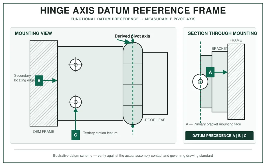
Use One Datum Scheme Across Hinge Stations
On a long door, separate hinge stations must be traceable to the same frame datums. If the upper hinge is dimensioned from the top edge, the lower hinge from the bottom edge and the frame length has its own tolerance, their axes can satisfy local dimensions but disagree in the assembly. Basic dimensions from one datum reference frame make the intended nominal relationship explicit. The associated geometric tolerance then defines the permitted three-dimensional zone around that relationship.
The common scheme should identify which organization controls each contributor. The hinge supplier can control the axis relative to the hinge mounting interface. The frame supplier can control reinforcement and mounting features relative to the frame datums. The OEM assembly drawing controls how the two interfaces meet. Assigning the entire installed-axis requirement to the purchased hinge is ineffective if the mounting flange, weldment or fastener clearance dominates the final location.
A common centerline note is not enough
A centerline drawn through multiple hinges communicates design intent, but it does not by itself define a measurable tolerance zone. The drawing still needs datum references, basic locations, a feature control frame or a defined functional-gage requirement, and an inspection state. Without those elements, “hinges to be coaxial” can be interpreted as a visual alignment note, a pin-fit requirement or a surface-runout requirement. Those are different acceptance tests.
Also decide whether the bores are one controlled pattern or several independently controlled features. Separate callouts can create separate permissible zones even when the nominal centerlines coincide. A pattern or multi-level position scheme can refine feature-to-feature alignment while also locating the group to the assembly datums, but its segments and datum references must be interpreted under the selected GD&T standard. Do not assume that identical numbers beside each bore create one shared zone.
Coaxiality Is the Function, Not Always the Symbol
Engineers commonly use coaxiality to describe the functional requirement that two or more pivot features share an axis. The OEM drawing should translate that function into a specific control. In current ASME practice, position is commonly used when the derived axis of a bore or pin must be located and oriented to datums. Runout is used when variation of an actual cylindrical surface during rotation about a datum axis is the concern. Form controls address the quality of one feature but do not locate it to another station.
Standard boundary: ASME Y14.5-2018 (R2024) provides the language and rules for geometric dimensioning and tolerancing. It does not prescribe a universal hinge-axis tolerance, select the manufacturing process or define the installed condition for a particular OEM door.
| Control | What it can communicate | Appropriate hinge-axis use | What it does not solve alone |
|---|---|---|---|
| Position | A cylindrical tolerance zone for a derived axis, located and oriented from a datum reference frame | Locating bore or pin axes at one or multiple hinge stations | Local bore form, surface finish and all rotating-surface variation |
| Perpendicularity / parallelism | Axis or surface orientation to a datum | Preventing tilt when lateral axis location is controlled separately | Translational location of the axis |
| Circular or total runout | Surface variation while the feature rotates about a datum axis | Bearing seats, pin diameters or rotating cylindrical surfaces where surface behavior matters | Nominal axis location unless the datum structure and dimensions establish it |
| Straightness / cylindricity | Form of one line element, median line or cylindrical surface | Controlling a long pin or bore whose own form can cause binding | Relationship to another hinge or assembly datum |
| Profile | A boundary for a complex surface or coordinated mounting geometry | Controlling formed or cast mounting interfaces that establish hinge position | A clear pivot-axis requirement unless the axis-defining features are included appropriately |
Do not place a generic “coaxiality tolerance” beside the drawing and leave the supplier to select the measured feature. State which bore, pin diameter, bushing seat or gage diameter creates the axis. State whether the control applies to each feature independently, to a pattern as a group or to the final installed assembly. The word describes the goal; the feature control frame and drawing notes create the acceptance requirement.
Position, Orientation and Form Are Different Problems
A positional tolerance on a short bore may allow an axis to tilt within its cylindrical zone. That may be acceptable for a compact hinge but significant when the bore directs a long pin or when two hinges are far apart. Conversely, a perpendicularity control can keep a bore axis square to the mounting plane while allowing the entire axis to move laterally. If both location and orientation affect assembly, the selected control scheme must constrain both.
Form is a separate contributor. A bore can have an acceptable derived axis but still be tapered, lobed or bowed enough to create local interference. A long pin can be correctly located at its ends but insufficiently straight. Do not consume the complete axis-location tolerance trying to compensate for uncontrolled form. Identify the surface or median-line behavior that affects the bearing contact, then assign a form requirement only where the functional risk justifies it.
Interrupted knuckles need a declared evaluation feature
A hinge knuckle presents several separated bore segments rather than one continuous cylinder. If each segment is evaluated independently, every local derived axis can pass while their combined path rejects or bends the pin. The drawing should show whether the segments form one controlled pattern, whether one segment establishes a datum axis, and which diameter or derived feature is used for evaluation. The inspection program must then sample enough of the interrupted geometry to test that stated relationship.
For a purchased hinge, the supplier may retain responsibility for the internal knuckle-to-pin relationship while the OEM controls the mounting interface and installed axis. The OEM does not need proprietary process dimensions to define this boundary. It needs a measurable external interface, a functional pivot requirement and an agreed verification method. Where interrupted surfaces are impractical for routine coordinate measurement, a controlled functional gage can complement—not silently replace—the drawing requirement.
Choose material-boundary modifiers from the fit function
Position at maximum material condition can allow bonus tolerance as the bore departs from its smallest permissible size or the pin departs from its largest permissible size. This can support functional assembly and gaging when the remaining clearance is what matters. Regardless of feature size may be more appropriate when axis location must remain controlled independently of actual size. The drawing team should make this choice from the fit and inspection concept, not add a modifier simply because the CAD template offers one.
Mounting Holes Do Not Automatically Define the Pivot
A rectangular hole pattern can locate a hinge leaf, but its functional effect depends on fastener clearance, slot direction, countersink seating, clamping friction and the stiffness of the leaf and frame. When holes are deliberately oversized to permit installation adjustment, they cannot simultaneously be treated as a repeatable precision datum unless a fixture or another locating feature establishes the final position.
Keep the procurement question separate from the axis question. The hinge mounting-hole pattern still needs the correct spacing, diameter, hole type and edge distances. This article addresses what those holes locate and whether their tolerance chain can preserve the functional pivot axis.
If the assembly requires adjustment, document the adjustment as a controlled process. Identify the alignment shaft, fixture, temporary fastener condition or measured axis used before final tightening. Otherwise, the drawing may demand tight axis location while the assembly method permits the hinge to settle anywhere inside the clearance envelope.
Allocate Tolerance From Door-Level Function
There is no responsible universal coaxiality value for an OEM hinge drawing. The allowable error depends on hinge spacing, door width, pin-to-bore clearance, bearing length, leaf stiffness, frame stiffness, seal compression, latch engagement, manufacturing process and the inspection state. Begin with what the assembly may do—not with a familiar decimal from another drawing.
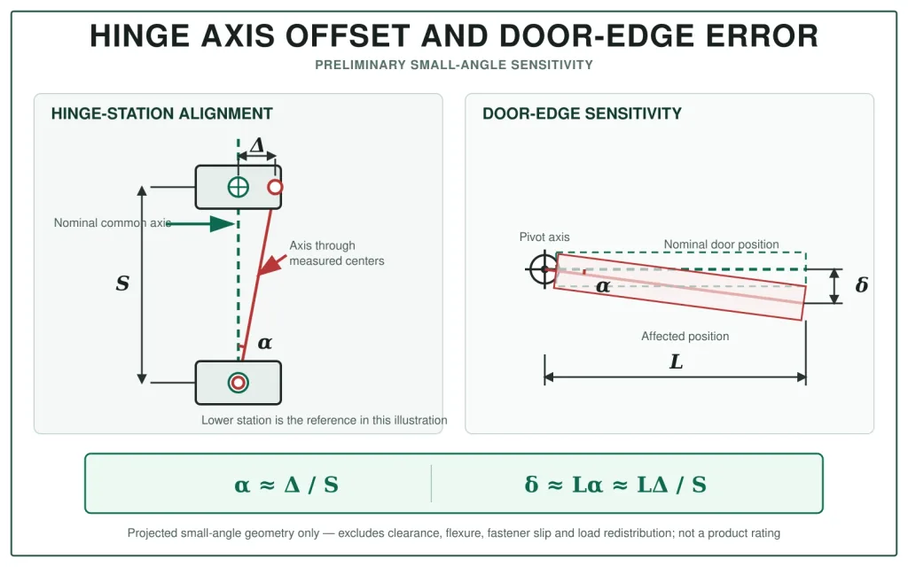
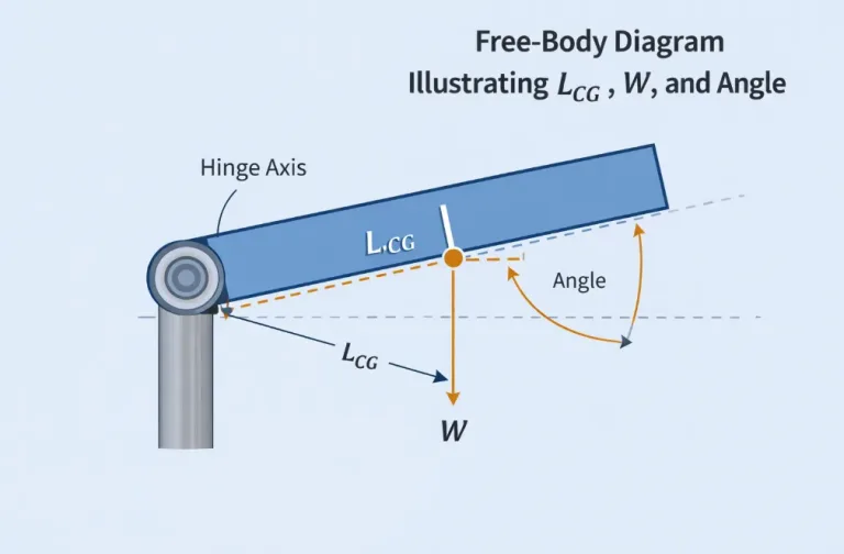
For two nominal hinge stations separated by distance S, a relative lateral center offset Δ creates an approximate line angle α. If an observed door edge is distance L from the pivot axis, that angular error can appear as an edge displacement δ. Under a small-angle assumption:
α ≈ Δ / S
δ ≈ Lα ≈ LΔ / S
Use: preliminary sensitivity analysis between hinge-station alignment and a door-level gap or latch observation.
Limit: this simplified geometry does not include elastic bending, clearances, local bore form, fastener slip, seal force or load redistribution. It is not a product rating or a drawing acceptance equation by itself.
The relationship explains why the same local offset can have different consequences on a compact lid and a wide industrial door. It also shows why moving hinge stations farther apart can reduce angular sensitivity, while a flexible frame may erase that theoretical advantage. The structural side of that decision belongs in the separate guide to hinge spacing and frame stiffness; this page uses the result only to allocate the axis-control budget.
Build an axis-specific tolerance budget
List every contributor between the datum simulator and the final pivot feature. Typical contributors include mounting-plane flatness, bracket profile, hinge-axis position within the hinge, frame-hole location, fastener clearance, local flange rotation, weld distortion, coating buildup and assembly fixture error. Do not automatically add every drawing tolerance arithmetically; identify whether contributors are biased, independent, adjustable or constrained by assembly contact. The objective is traceability, not a mathematically impressive stack that does not resemble the build.
Illustrative design conflict: an OEM tightens the hinge bore position while retaining a flexible, unsupported mounting flange. The hinge supplier improves the bore, but final assemblies still bind after fastener tightening because the flange rotates. The correct response is not automatically a tighter hinge tolerance. The drawing and fixture strategy must control the weak mounting zone or define the clamped inspection state.
Define Free, Clamped and Finished Inspection States
A geometric callout can be precise while the inspected condition remains ambiguous. A thin hinge leaf measured free on a CMM may change when clamped to the frame. A welded bracket may be machined before welding but inspected after distortion. Paint, plating or powder coating can alter seating surfaces and bore clearances. The print or associated inspection plan must say which state controls acceptance.
State the condition only as tightly as the function requires. Relevant items can include:
- loose part, hinge subassembly or final OEM assembly;
- free state, fixture-clamped state or installed fastener condition;
- before or after welding, heat treatment and final coating;
- pin installed or removed, and any defined gage diameter;
- door angle, external load and seal or cable condition during inspection;
- fastener type, tightening sequence and project-defined torque where these affect seating.
Do not copy installation instructions into the drawing. Instead, reference the controlled assembly or inspection specification that establishes the state. Physical setup, alignment correction and final movement checks remain installation work; use the torque hinge installation guide for that task rather than expanding this page into a second installation procedure.
Inspection Must Recreate the Datum Scheme
The inspection setup should contact the same functional surfaces, in the same datum order, that the drawing uses. If the CMM aligns to a convenient raw edge while the print uses the machined mounting plane and locating step, the result does not verify the drawing. If a functional shaft is passed through several bores while the assembly is unconstrained, it may pull flexible parts into alignment and hide the free-state error.
| Characteristic | Possible inspection method | What it demonstrates | Important limitation to state |
|---|---|---|---|
| Axis position of a machined bore | CMM or suitable coordinate measurement from A|B|C | Derived-axis location and orientation to the datum reference frame | Sampling strategy, bore form and datum simulation must be defined consistently |
| Common passage through several hinge stations | Project-defined alignment shaft or functional gage | Assembly accepts the specified gage in the specified state | Gage size, insertion force, clamping, gravity direction and acceptance depth need definition |
| Rotating pin or bearing-seat surface | Mandrel and indicator, or CMM runout evaluation | Surface variation relative to the established datum axis | Runout does not replace all size, form or position controls |
| Large door/frame hinge stations | Portable coordinate, optical or laser measurement tied to assembly datums | Three-dimensional station relationship on the final structure | Environmental stability, target setup and measurement uncertainty can dominate a tight limit |
| Door movement and latch alignment | Controlled functional motion check | System-level acceptance under the stated load and angle | A pass does not isolate hinge-axis error from frame flex, seals, cables or latch adjustment |
A shaft that “goes through” is valuable when it is intentionally designed as a functional gage. It is weak evidence when the shaft diameter, straightness, insertion direction and allowable force are unspecified. Likewise, a digital inspection report is not automatically stronger than a gage check. The best method is the one that measures the stated requirement with suitable resolution and reproduces the functional datum condition.
Drawing Notes That Remove Supplier Guesswork
The feature control frame should carry the geometric requirement. Notes should define the acceptance state and any project-specific functional method that the symbols cannot communicate alone. Avoid notes that merely repeat “all hinge axes must align” or “no binding permitted.” They describe desired outcomes without identifying features, datums or measurement conditions.
The following is a drafting pattern, not a copy-ready tolerance specification. Replace bracketed fields only after the functional stack and inspection capability have been reviewed:
AXIS-CONTROL NOTE PATTERN — PROJECT-SPECIFIC
1. DATUM A SHALL BE ESTABLISHED BY [FUNCTIONAL MOUNTING SURFACE] IN [FREE / CLAMPED / INSTALLED] CONDITION.
2. DATUMS B AND C SHALL BE ESTABLISHED BY [FUNCTIONAL LOCATING FEATURES] IN THE ORDER SHOWN.
3. THE DERIVED AXES OF [IDENTIFIED BORES / PINS / GAGE DIAMETERS] SHALL MEET THE FEATURE CONTROL FRAMES SHOWN RELATIVE TO A|B|C.
4. MULTIPLE HINGE STATIONS SHALL BE VERIFIED ON THE [PART / SUBASSEMBLY / FINAL ASSEMBLY] AT [DEFINED PRODUCTION STATE].
5. WHERE A FUNCTIONAL GAGE IS REQUIRED, GAGE DIAMETER, STRAIGHTNESS, INSERTION DIRECTION, ALLOWABLE FORCE AND ACCEPTANCE DEPTH SHALL FOLLOW [CONTROLLED SPECIFICATION].
6. COATING, WELDING AND FASTENER CONDITION AT INSPECTION: [PROJECT DEFINITION].
1. DATUM A SHALL BE ESTABLISHED BY [FUNCTIONAL MOUNTING SURFACE] IN [FREE / CLAMPED / INSTALLED] CONDITION.
2. DATUMS B AND C SHALL BE ESTABLISHED BY [FUNCTIONAL LOCATING FEATURES] IN THE ORDER SHOWN.
3. THE DERIVED AXES OF [IDENTIFIED BORES / PINS / GAGE DIAMETERS] SHALL MEET THE FEATURE CONTROL FRAMES SHOWN RELATIVE TO A|B|C.
4. MULTIPLE HINGE STATIONS SHALL BE VERIFIED ON THE [PART / SUBASSEMBLY / FINAL ASSEMBLY] AT [DEFINED PRODUCTION STATE].
5. WHERE A FUNCTIONAL GAGE IS REQUIRED, GAGE DIAMETER, STRAIGHTNESS, INSERTION DIRECTION, ALLOWABLE FORCE AND ACCEPTANCE DEPTH SHALL FOLLOW [CONTROLLED SPECIFICATION].
6. COATING, WELDING AND FASTENER CONDITION AT INSPECTION: [PROJECT DEFINITION].
Do not put the actual tolerance only in a prose note when a geometric control can express it unambiguously. Do not specify an inspection device as a substitute for the product requirement unless acceptance is intentionally defined by a functional gage. Finally, do not promise interchangeability from the hinge drawing if the OEM frame datums and mounting-zone stiffness remain uncontrolled.
Review the Axis Before Releasing the Drawing
This review is deliberately limited to the pivot-axis definition. It should be completed alongside—not in place of—the broader drawing, application and supplier reviews.
- Name the functional axis. Identify the actual pin, bore, bushing seat, knuckle set or gage diameter that establishes rotation.
- Choose the drawing level. Decide whether the requirement belongs on a component, hinge subassembly or OEM door/frame assembly.
- Follow assembly contact. Make datum A, B and C reproduce the stable seating and locating sequence.
- Use one reference frame. Relate separated hinge stations to shared assembly datums rather than independent edge chains.
- Select the control by function. Use position for axis location/orientation, runout for rotating-surface behavior and form controls only for local form risks.
- Allocate a justified limit. Connect the permitted axis variation to gap, latch, bearing, seal or motion sensitivity and to the complete manufacturing stack.
- State the inspected condition. Define free or clamped state, production stage, fastener condition and door angle when they affect results.
- Match inspection to the callout. Confirm the supplier and OEM can reproduce the datum simulation and resolve the required tolerance.
If one of these decisions remains unknown, mark it as project-specific instead of filling the gap with a guessed tolerance. A drawing that exposes an unresolved engineering input is safer than one that hides it behind a precise but unsupported number.
When hinge axis datums, controlled pivot features and the inspection state all reference one assembly scheme, the supplier and OEM can verify the same axis instead of interpreting “coaxial” differently.
Hinge Axis Datum and Coaxiality FAQ
What datum feature should establish a hinge axis?
Use the stable physical feature or feature set that reproduces how the hinge seats and locates in the assembly. A mounting surface is often the primary datum feature, but the correct hierarchy depends on the actual contact sequence. Do not default to a flexible sheet edge or clearance-hole pattern simply because it is easy to dimension.
Is hinge coaxiality the same as concentricity?
No. Coaxiality is commonly used as a functional description: two or more hinge features should share an axis. Concentricity is a legacy or standard-specific geometric term and should not be used as a generic replacement. A new drawing should select position, runout or another control according to the feature and function being verified.
Should an OEM drawing use position or runout for hinge bores?
Use position when the derived bore axis must be located and oriented relative to the assembly datums. Use runout when variation of the actual cylindrical surface during rotation about a datum axis is the functional concern. Some designs need additional size or form controls; the two symbols are not interchangeable.
Can mounting holes control hinge-axis alignment?
They can contribute when the hole pattern, fastener fit, seating features and mounting-zone stiffness create repeatable location. Oversized or slotted holes intended for adjustment do not by themselves establish a precision axis. In that case, the drawing or assembly specification should define the fixture or functional alignment method used before final tightening.
How should multiple hinge axes be inspected?
Inspect them from the shared OEM datum reference frame and in the production state defined by the drawing. Depending on size and function, this may use a CMM, portable coordinate system or a project-defined alignment shaft. A shaft-fit test is valid only when its diameter, straightness, insertion condition and acceptance rule are controlled.
Send the Axis-Control Drawing Inputs
For a project-specific discussion, send the hinge or bracket drawing, the OEM mounting interface, the features that establish rotation, the installed hinge spacing, the assembly state and the inspection method available to both parties. HTAN can confirm which hinge dimensions and supplier data are available and identify which axis requirements must remain under the OEM drawing authority.
Send the drawing and assembly inputs
 English
  한국어
한국어  Русский
  Español
  Italiano
  Deutsch
  Français
  Português