

What to Include in an Industrial Hinge Drawing
An industrial hinge drawing can show the leaf length, hole spacing, material, and finish—and still fail to define the part the equipment needs. The holes may fit, but the pin centerline sits at the wrong offset. The drawing may say “holds position,” but it does not identify the direction, angle range, or verification method. The 3D model may show one geometry while the PDF carries another revision.
An industrial hinge drawing checklist should remove those interpretation gaps before the drawing is released. The supplier needs to know which file controls, where the functional axis sits, how the leaves locate on the equipment, what motion is required, which materials form the joint, and which referenced method verifies the requirement. The drawing is not a product brochure. It is the controlled definition of the part.
Start With the Assembly Interface
Do not begin with the outline of an isolated hinge. Begin with the door, lid, machine guard, enclosure frame, access panel, or equipment bracket that the hinge must connect. The hinge geometry should follow the assembly interfaces, not the other way around.
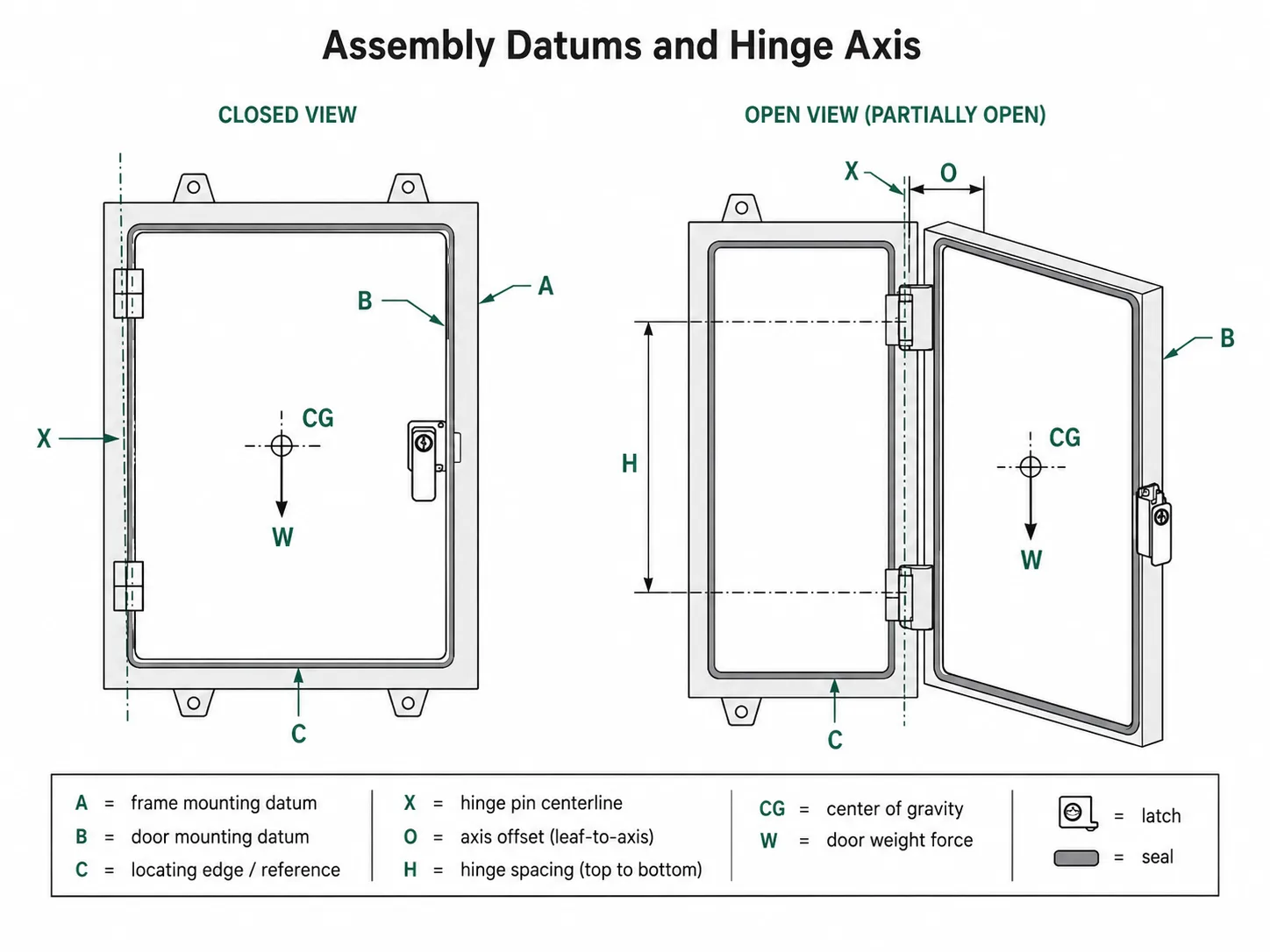
Before drawing the hinge, define the primary mounting face, the locating edge, the required pin centerline, the closed position, the open or removal envelope, and the parts that share the door edge. Include the latch, gasket, cable, ground strap, opening stop, adjacent panel, and service path where they affect the hinge.
- Moving assembly: complete weight, center of gravity, orientation, handle, window, brackets, and attached hardware.
- Door-side interface: material, thickness, reinforcement, mounting face, locating edge, hole or weld pattern, and available tool access.
- Frame-side interface: material, thickness, reinforcement, mounting face, opening flange, gasket line, and adjacent structure.
- Motion: opening range, resistance direction, hold position, stop responsibility, removal direction, or spring behavior.
- Environment: moisture, cleaner, dust, coolant, salt, temperature, vibration, and corrosion exposure.
- Service condition: installation sequence, replacement method, removable parts, retained hardware, and access clearance.
If the project has not yet decided whether it needs a standard part or a custom-controlled drawing, resolve that question first with the standard or custom hinge decision. This article begins when the OEM is ready to control the hinge definition.
Drawing Authority and Revision Control
A correct feature on an uncontrolled file is not a released requirement. State which document controls the hinge definition and how the other files support it.
Which File Is the Master?
Projects often send a PDF drawing, STEP model, native CAD file, assembly screenshot, and email notes at the same time. The supplier should not decide which one wins when they disagree. The OEM must identify the master definition.
- If the 2D drawing controls dimensions, tolerances, materials, and notes, state that the 3D model is supplemental unless otherwise identified.
- If the 3D model or model-based definition controls geometry, identify the controlling model revision and the PMI or referenced specification that controls tolerances and notes.
- If the assembly view is illustrative only, label it accordingly.
- Do not allow an old STEP file to remain attached to a newly revised PDF without a revision cross-check.
- When a conflict exists, require clarification before tooling or manufacture. The supplier should not select the more convenient interpretation.
Identity, Configuration, and Change Control
- Part and drawing identity: customer part number, drawing number, supplier part number where assigned, and revision.
- Drawing status: quotation, prototype, sample, approved, or production release.
- Units and projection: identify the unit system and projection convention; do not rely on PDF display scale.
- Configuration: hinge type, left-hand, right-hand, reversible condition, door leaf, frame leaf, installed orientation, and motion direction.
- Included components: pins, bushings, washers, springs, friction parts, rings, covers, fasteners, lubricant, or other supplied elements.
- Revision description: explain whether the change affects tooling, interchangeability, inspection, function, finish, or an approved sample.
State the applicable ASME Y14.5 edition or the company drawing standard in the title block or referenced specification. ASME Y14.5 provides the language for dimensioning and tolerancing. It does not select the hinge axis, acceptable sag, cycle requirement, or project acceptance limit.
The Hinge Axis Is the Primary Reference
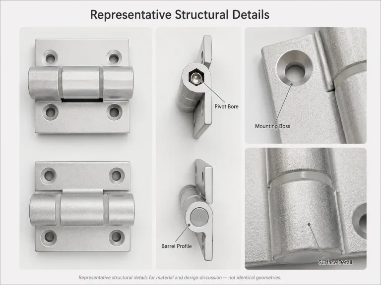
The pin centerline controls how the door moves relative to the frame. It affects reveal, gasket compression, latch approach, cable movement, opening clearance, and removable-door separation. Yet many drawings dimension the leaf outline carefully and leave the functional axis implied by the rolled knuckle.
Locate the hinge axis from mounting datums that exist on the assembled part. A practical structure may use the primary mounting face as datum A, a locating edge as datum B, and a hole or secondary edge as datum C. The exact scheme depends on manufacturing and inspection. The purpose is to control the installed relationship, not to decorate the drawing with GD&T symbols.
- Dimension the pin centerline from the functional mounting face and locating edge.
- Define the relationship between the door-side and frame-side mounting faces.
- Control leaf flatness or profile where rocking changes the installed axis.
- State whether the axis is inspected in the free state, clamped state, assembled state, or a defined fixture.
- Use parallelism, perpendicularity, or position only where the assembly function needs it.
- Do not define the functional axis only from a variable knuckle outside diameter unless that surface is the intended inspection reference.
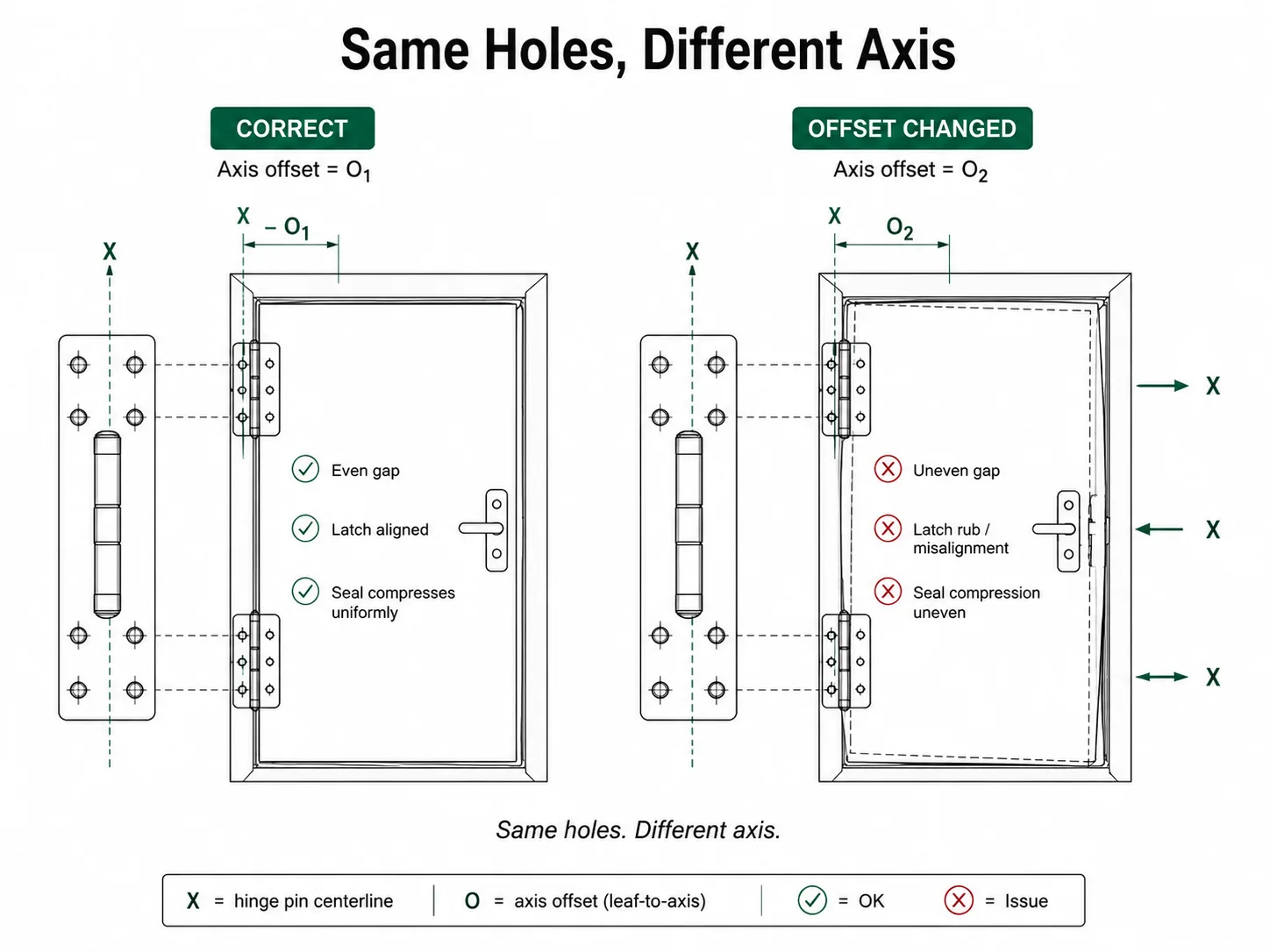
The holes align. The door still shifts. Two hinges can share the same leaf size and mounting pattern while placing the pin centerline at different offsets from the mounting face. Both parts bolt on. One moves the door outward, changes the gasket approach, and makes the latch side rub the frame. The installation problem began in the axis definition, not in the hole spacing.
This is an illustrative engineering scenario, not a customer project record or product test claim.
Mounting Faces, Holes, and Fasteners
The drawing does not need to reteach every hole type. It does need to integrate the released pattern with the mounting faces, functional datums, fastener direction, and assembly access.
| Mounting Interface | What the Drawing Must Control | Failure if It Is Left Implied |
|---|---|---|
| Door-side and frame-side faces | Contact surface, leaf assignment, installed orientation, and flatness/profile where required | The leaf rocks, twists, or is pulled flat by the fasteners |
| Pattern location | Basic or coordinate locations from functional datums and the relationship to the pin centerline | The holes fit but the installed hinge axis moves |
| Slot direction | Allowed adjustment direction, slot envelope, and final locating method | The assembly adjusts in the wrong direction or remains underconstrained |
| Fastener side | Head side, nut or insert side, countersink/counterbore side, and rear access | The fastener cannot be installed or the wrong leaf is mounted outward |
| Tool envelope | Driver, wrench, welding torch, fixture, and inspection access in the assembly | The hinge fits the model but cannot be installed or inspected |
| Welded interface | Weld land, prohibited weld zone, fixture datum, and post-weld finish repair | Heat or weld sequence changes the axis or damages the joint |
| Mounting hardware | Customer- or supplier-provided status, reference fastener, washer, locking method, and joint condition | The OEM and supplier validate different mounting joints |
Use the dedicated hinge mounting hole pattern page when the task is measuring or matching an existing pattern. This page only controls how the approved pattern is located and used on the OEM drawing.
Dimension the Motion Envelope From the Assembly
A hinge is not only a closed-position part. The released drawing should protect the positions that matter to installation, operation, adjustment, and service.
Closed Position
Control the leaf stack, axis offset, door reveal, overlap, flush relationship, gasket line, and latch approach. “Flush” is not a measurable requirement unless the drawing ties it to defined assembly surfaces.
Open Position
Show the required opening range and clearance to flanges, handles, walls, cables, adjacent panels, guards, or other doors. If a separate structure carries the opening-stop load, state that. Do not let the supplier assume the hinge itself is the structural stop.
Adjustment and Removal
For an adjustable hinge, preserve access to the adjustment feature after installation. For a lift-off or removable hinge, define the separation direction, minimum lift or tilt clearance, removal angle, retention release, pin direction, and the condition of cables or ground straps. For a concealed hinge, show the pocket and cutout envelope.
The 3D assembly can illustrate these positions, but the controlling drawing or referenced model must identify the dimensions that protect them. A supplier should not have to measure a screenshot to discover the available swing or removal clearance.
Functional Requirements and Referenced Verification
“Heavy duty,” “smooth,” “holds at any angle,” “long life,” and “corrosion resistant” are descriptions, not controlled requirements. The drawing should state the function and point to the method that verifies it.
For a door or lid, the static moment about the hinge line begins with:
M = W × d
W is weight force, not mass. If the project input is mass, convert it to weight before calculating the moment. Newtons multiplied by meters give N·m; newtons multiplied by millimeters give N·mm. The equation is a static starting point and does not include impact, vibration, user input, stop load, frame movement, unequal hinge sharing, or the supplier’s rating method.
| Function | Controlled Drawing Requirement | Referenced Verification Method or Record |
|---|---|---|
| Free-swinging load support | Moving weight, CG, orientation, hinge quantity and spacing, opening range, and load direction | Rating basis or representative load-path test with the mounting condition and allowable retained alignment |
| Torque or position control | Resistance direction, angle range, required hold region, allowed spring-back, and user-force point where relevant | Torque-angle method with fixture, speed, temperature, conditioning, direction, and sample identity |
| Detent | Detent angles, direction, engagement/release behavior, and permitted angular play | Defined engagement and release measurement before and after the agreed use condition |
| Spring return or assist | Direction, start/end angles, return or assist behavior, and stop responsibility | Force-angle or torque-angle method under the defined assembly and temperature condition |
| Opening stop | Stop angle and identification of whether the hinge or a separate structure carries the load | Stop-load method, event count, impact condition, and deformation acceptance |
| Lift-off or removable | Removal direction, angle, clearance, pin direction, retention, and installed captive condition | Removal/reinstallation demonstration and alignment check on the representative assembly |
| Environmental resistance | Material system, exposure, appearance limit, and post-exposure function | Referenced environmental method followed by the defined functional retest |
| Cycle retention | Representative motion profile and the function that must remain after cycling | Initial, intermediate, and final measurements with load, angle, speed, dwell, and environment |
Do not add a universal safety factor, cycle count, torque percentage, or corrosion duration to make the drawing appear complete. When the method is too detailed for a drawing note, issue a separate test specification and reference its number and revision. Keep the drawing, test specification, model, and controlled record tied to the same part and revision.
Material Stack and Pin Retention
A leaf-material note does not define the complete hinge. The joint may contain a different pin, bushing, washer, spring, friction element, retaining ring, fastener, lubricant, or insert. Each can change corrosion, wear, torque, play, electrical continuity, cleanability, and disassembly.
- Leaves: material grade or approved specification, thickness, condition, and forming direction where relevant.
- Pin or shaft: material, diameter, hardness or treatment where required, and surface condition.
- Bushings and washers: material, quantity, position, thickness, and replaceable or permanent status.
- Spring or friction parts: controlled specification where the function depends on them.
- Lubricant: identity or performance requirement only when it is part of the released design.
- Fasteners: supplied status, material, finish, locking method, and galvanic relationship to the leaves and equipment.
- Finish: process, controlled surfaces, masking, thread condition, weld lands, appearance reference, and thickness where fit depends on it.
Retention Belongs on the Released Definition
State the selected pin-retention method, pin direction, permitted axial movement or end play where critical, removable or captive condition, and any required inspection access. Do not use this page to compare formed ends, rings, threads, cross-pins, or vibration tests in detail. That task belongs to the hinge pin retention specification page.
Tolerances That Protect Function
Tight tolerances on every dimension increase manufacturing and inspection cost without guaranteeing a better hinge. Control the features that protect mounting, axis location, movement, interchangeability, and the selected output.
Separate dimensions into functional interfaces, manufacturing dimensions, and reference dimensions. The first group controls the installed result. The second supports production. The third communicates useful information but is not independently toleranced.
| Characteristic | Why Specific Control May Be Needed | Drawing Action | Inspection Condition |
|---|---|---|---|
| Pin centerline position | Controls door path, reveal, sealing approach, latch alignment, and interchangeability | Locate the axis from functional datums | State free, clamped, assembled, or fixture condition |
| Mounting-pattern position | Controls assembly location and load transfer | Use a datum-based location method tied to the installed relationship | Identify the fastener or gage condition |
| Leaf flatness or profile | Changes the installed axis when the leaf rocks or is pulled flat | Control the mounting face that affects the assembly | State whether the leaf is free or restrained |
| Leaf-to-axis offset | Moves the door even when the holes match | Dimension directly to the true pin centerline | Define the measurable datum surface |
| Alignment of hinge elements | Affects binding, paired-hinge load sharing, and wear | Use a measurable control or functional fixture | Define assembly state and hinge quantity where relevant |
| Pin end play | Affects rattle, interference, removal, and retention | State the permitted movement when function requires it | Define force, direction, and measurement point |
| Torque, detent, or spring output | Varies with angle, direction, speed, temperature, and conditioning | Reference the controlled verification method | State fixture and conditioning in the referenced specification |
A general title-block tolerance can remain useful for noncritical dimensions. It should not silently control the hinge axis, hole pattern, stop angle, pin end play, or functional output when those characteristics require a different interpretation.
Turn the Requirement Into Drawing Callouts
The drawing should not leave the engineer with a list of topics but no usable language. The following format shows how to organize controlled callouts without inventing project values. Replace the brackets with released project data or a referenced specification.
INDUSTRIAL HINGE DRAWING RELEASE FORM
------------------------------------------------------------

DOCUMENT AUTHORITY

Controlling definition:     2D drawing / 3D model / MBD dataset
Controlling revision:
Supplemental files:        assembly view / STEP / native CAD
Conflict rule:             OEM clarification required before tooling or manufacture


CONFIGURATION

Hinge type:                free-swing / torque / detent / spring / lift-off / other
Hand:                      left / right / reversible
Door leaf identification:
Frame leaf identification:
Installed orientation:      see view / assembly
Included components:        pin / bushing / washer / spring / ring / fastener / other


FUNCTIONAL AXIS

Primary mounting datum:
Secondary locating datum:
Pin centerline location:
Leaf-to-axis offset:
Inspection condition:       free / clamped / assembled / fixture


MOUNTING INTERFACE

Mounting pattern detail:
Fastener condition:
Fastener side:
Slot adjustment direction:  if applicable
Tool access view:
Weld land:                 if applicable
Prohibited weld zone:       if applicable


MOTION

Closed position:            see view
Required opening range:
Stop responsibility:        hinge / separate structure
Removal direction:          if applicable
Removal clearance:          if applicable
Adjustment access:          if applicable


MATERIAL SYSTEM

Leaf material:
Leaf thickness:
Leaf condition:
Pin material:
Pin diameter:
Pin treatment:
Bushing / washer:
Spring / friction element:
Lubricant:
Fastener:
Finish:
Masked or uncoated surfaces:


PIN RETENTION

Retention method:
Pin direction:
Permitted axial movement:
Permitted end play:
Condition:                 removable / captive


FUNCTION

Required output:            load / torque / detent / spring / stop / other
Direction:                  opening / closing / both
Angle or operating range:
Environment:
Conditioning:
Verification specification:
Specification revision:
Controlled record:         report / inspection identifier


RELEASE CHECK

2D drawing synchronized:    yes / no / not applicable
3D model synchronized:      yes / no / not applicable
Assembly view synchronized: yes / no / not applicable
Referenced specifications:  current / revision mismatch
Engineering review required: yes / no
Released by:
Release date:
Editing note: Complete only the fields that apply to the released hinge. Delete non-applicable fields instead of leaving empty requirements on the production drawing.
This template is a structure, not a universal note set. Delete fields that do not apply. Add project-specific interfaces that do. Do not copy an empty requirement onto a production drawing simply because it appears in the template.
The Drawing Release Checklist
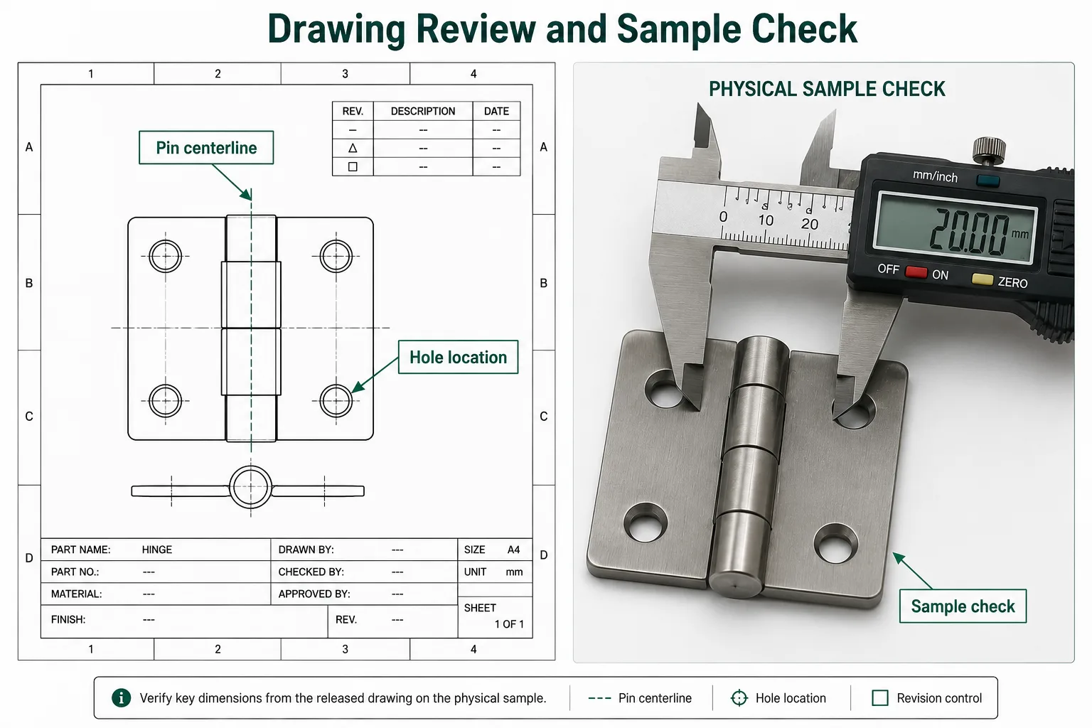
Use this checklist before the drawing is released for quotation, prototype manufacture, or a controlled sample. A missing field does not always mean the drawing is wrong. It means the OEM should decide whether the requirement belongs on the drawing, in the controlling model, or in a referenced specification.
| Drawing Area | Release Question | Required OEM Action |
|---|---|---|
| Authority | Does the drawing identify which file controls when the PDF, model, and assembly view disagree? | State the master definition and conflict rule |
| Identity | Are part number, drawing number, revision, status, units, projection, and applicable drawing standard controlled? | Complete the title block and revision description |
| Configuration | Are hinge type, handing, door/frame leaf, motion direction, installed orientation, and supplied components unambiguous? | Add configuration notes and an installed view |
| Datums | Do the datums come from reproducible assembly interfaces? | Define the mounting face and locating features |
| Hinge axis | Is the pin centerline located from the functional datums? | Add the axis and offset controls |
| Mounting interface | Is the approved pattern connected to datums, fastener side, tool access, and mounting condition? | Release the interface and hardware assumptions |
| Motion envelope | Are closed, open, adjustment, and removal positions protected? | Identify the critical views and clearances |
| Function | Are load, direction, angle, torque, detent, spring, stop, or removal requirements stated without vague terms? | Write the controlled requirement and reference its verification method |
| Material stack | Are leaves, pin, bushings, washers, springs, friction parts, lubricant, fasteners, and finish controlled where necessary? | Complete the BOM or material notes |
| Retention | Are the pin-retention method, direction, captive/removable condition, and critical end play defined? | Add the selected retention callout |
| Tolerances | Do specific tolerances protect the axis, pattern, mounting faces, offsets, and output without over-tolerancing the part? | Review critical dimensions and measurement conditions |
| Verification reference | Does every performance requirement point to a controlled method or record? | Reference the specification number and revision |
| Synchronization | Do the PDF, model, assembly view, and referenced specifications carry consistent identifiers and revisions? | Release one synchronized technical package |
Keep commercial quantity, tooling, lead time, packaging, logistics, and quotation validity in the RFQ document. Keep sample measurements, deviations, and approval decisions in the hinge sample approval checklist. The drawing should remain the controlled technical definition.
Send the Released Drawing and Assembly View
Include the controlled hinge drawing and the assembly view needed to interpret its datums, pin centerline, mounting faces, and motion envelope. HTAN can then determine whether an existing hinge or a custom quotation path is appropriate. Final fit and performance remain subject to the released requirement and assembly-level sample approval.
FAQs
What should be included in an industrial hinge drawing?
Include drawing authority and revision, hinge configuration and handing, functional datums, pin centerline, mounting interface, closed and open envelopes, material stack, pin retention, critical tolerances, functional requirements, and references to any separate verification specification. Keep commercial RFQ and sample-approval records outside the drawing.
Should the hinge pin centerline be dimensioned on the drawing?
Yes when the axis controls door position, reveal, gasket compression, latch alignment, motion clearance, interchangeability, or removable-door geometry. Locate it from functional mounting datums that can be reproduced and inspected rather than implying it only from the knuckle outside diameter.
Should hinge mounting holes be dimensioned from the hinge axis or the leaf edge?
Use the functional datums that reproduce the installed relationship. The hinge axis may be part of that relationship, but a raw leaf edge should not be used automatically when it does not locate the hinge in the assembly. Control the approved pattern from the mounting face and locating features that the OEM and supplier can inspect consistently.
When should a hinge drawing reference a separate test specification?
Use a separate specification when load, torque, detent, spring, stop, cycle, removal, or environmental verification requires a detailed fixture, direction, speed, angle, temperature, conditioning, measurement sequence, or acceptance method. Reference the specification number and revision on the drawing so the requirement and method stay synchronized.
Which file controls if the 2D hinge drawing and 3D model disagree?
The OEM must identify the controlling definition in the title block, model notes, or project specification. The supplier should not choose between conflicting files. If the master file and precedence rule are not clear, obtain written clarification before tooling or manufacture and update the released files to the same revision.



 English
  한국어
한국어  Русский
  Español
  Italiano
  Deutsch
  Français
  Português