

How to Specify Torque Hinges for Cabinet-Mounted Control and Service Panels
A cabinet-mounted control panel can hold correctly before wiring and still drift after the production harness is installed. Increasing hinge resistance may stop the movement, but the operator or technician can then struggle to reposition the panel or open it for rear-terminal access. The hinge is not working alone. Moving weight, center of gravity, touchscreen or button input, connector forces, cable loops, grounding straps, brackets, and paired-hinge alignment all appear in the final behavior.
Electrical cabinet torque hinges should therefore be specified from the operating and service tasks of the complete moving panel. The target is not maximum resistance or a vague promise to hold at any angle. The target is stable behavior at the required positions without excessive user force, cable strain, bracket movement, or dependence on an undefined stop.
This page covers control faceplates, cabinet-mounted HMI panels, instrument panels, and small service or inspection panels hinged directly to a cabinet, console, or internal compartment. For the main enclosure door, gasket, latch, grounding, load support, and complete hinge architecture, use the electrical enclosure hinge solution.
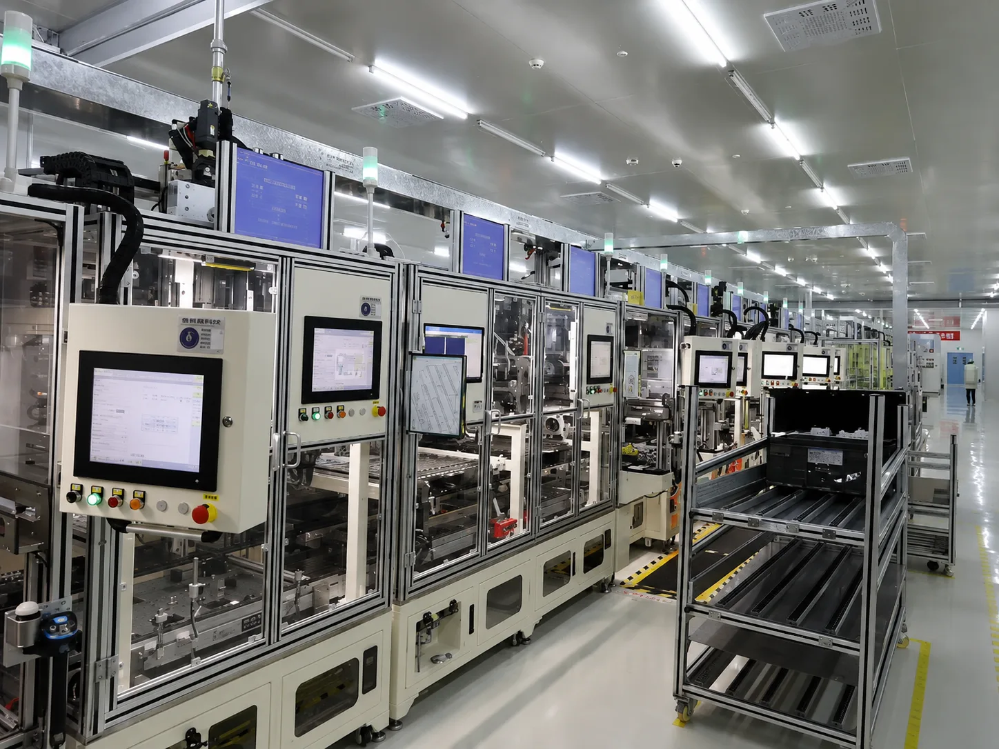
Panel Configurations That Need Position Control
Electrical cabinets use several kinds of displays, doors, and internal panels. The location of the pivot and the required movement determine whether torque hinges belong in the mechanism.
| Panel Configuration | Motion Requirement | Torque Hinges Are Useful When | Alternative or Separate Task |
|---|---|---|---|
| Fixed display in a cabinet door | No hinged movement at the display | Not applicable to the display itself | Review the door cutout, support, sealing, and wiring as part of the enclosure system |
| Display on an independent monitor arm | Reach, tilt, frequent user repositioning, and arm stability | The arm joint requires controlled display positioning | Use the industrial monitor arm torque hinges page |
| Control or HMI faceplate hinged directly to the cabinet | Normal operation plus rear-terminal or wiring access | The panel must move smoothly and remain at useful operating or service positions | A detent or stay may be simpler when only one or two fixed positions are required |
| Instrument panel that folds down for service | Controlled descent and stable access to rear components | The panel needs repositionable support rather than one rigid service angle | Use a stay or support when connector work requires a rigid reaction point |
| Small internal service or inspection panel | Remain clear of the technician, tools, or component-removal path | Intermediate position holding improves access and a separate prop would interfere | Standard hinges with a stay may be more direct for one defined maintenance position |
| Main electrical cabinet door | Load support, sag control, sealing, latch alignment, security, and access | Only when a specific position-control function has been identified | Complete cabinet-door selection belongs to the enclosure hinge solution |
The moving panel may carry a touchscreen, membrane keypad, selector switches, indicators, connectors, protective cover, internal brackets, and wiring. Include those parts in the moving mass and service-clearance model. A main cabinet door behind the panel is a separate load system unless both move about the same defined axis.
Operating Angle and Service Angle
The normal operating position is not necessarily the position needed for maintenance. An operator may use the HMI close to the cabinet face. An electrician may need the panel farther open to reach connectors, terminal blocks, fuses, or fasteners behind it. A component may require a third angle for removal.
Define each required position before selecting torque:
- Closed or stowed position: the panel is secured, protected, or flush with the cabinet.
- Operating position: the HMI is visible and usable without drift during normal touch or button input.
- Rear-service position: the panel remains clear while wiring, terminals, or internal components are inspected.
- Removal position: the panel and attached hardware do not block the path of a connector, module, or tool.
- Maximum permitted angle: a defined stop prevents cable overtravel, cabinet contact, or excessive hinge rotation.
Do not convert “several positions are useful” into an unsupported requirement to hold at every angle. A panel that only needs one normal operating position and one locked service position may be better served by a detent, stay, stop, or another support mechanism. Torque hinges add value when smooth repositioning and intermediate hold behavior are real operating requirements.
Holding Stability Versus Operating Effort
The hinge must resist the moment that tends to move the panel, but the operator or technician must still be able to reposition it. These requirements work against each other. Higher resistance can reduce drift. It also raises the force at the panel edge or handle.
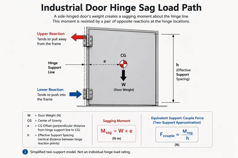
For an upward, downward, or inclined panel, the preliminary gravity moment changes with the perpendicular distance from the hinge axis to the center-of-gravity line:
Mg(θ) = W × d⊥(θ)
W is the complete moving-panel weight force. d⊥(θ) is the perpendicular moment arm at the evaluated angle. The relationship identifies positions that deserve review. It does not provide the final hinge model, torque tolerance, environmental allowance, or per-hinge value by itself.
Use the general torque hinge sizing method for complete calculation logic. This page stays with the cabinet-panel inputs that the calculation and sample test must represent.
Holding, Breakaway, and Running Resistance
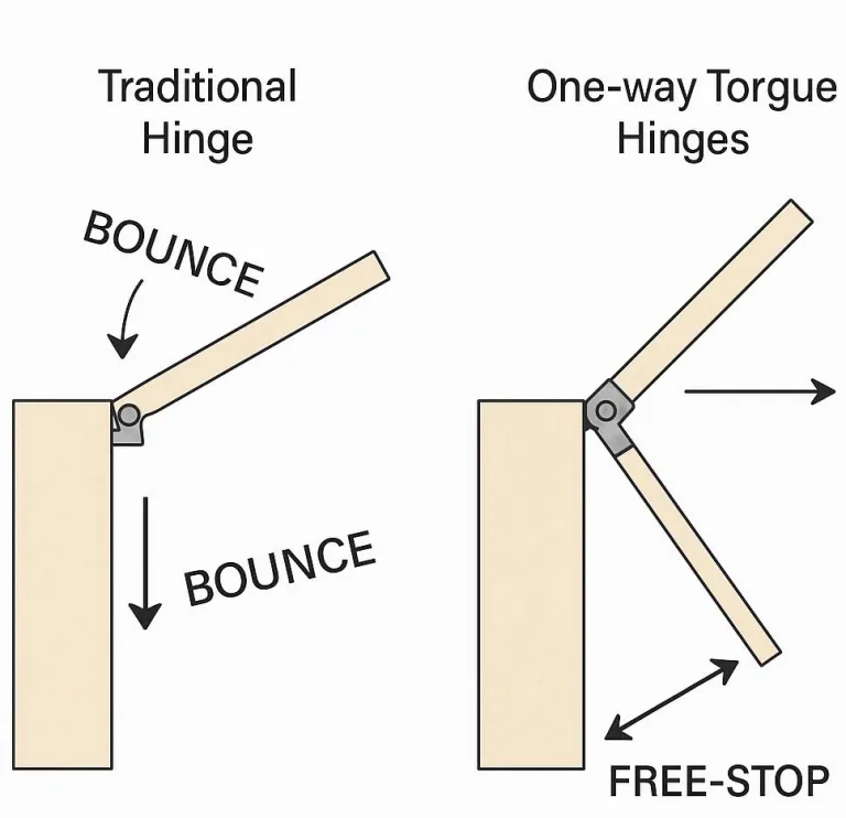
One nominal torque value cannot describe every part of the motion. Holding behavior describes whether the released panel remains at a required position. Breakaway resistance is the effort needed to start movement after rest. Running resistance is the effort while the panel is already moving. These values can differ, and direction can matter.
A panel can meet a static hold requirement and still feel unacceptable if breakaway is high or movement is uneven. The opposite also occurs: smooth movement on the bench, followed by slow drift after the production panel is released.
Direction and Adjustment Inputs
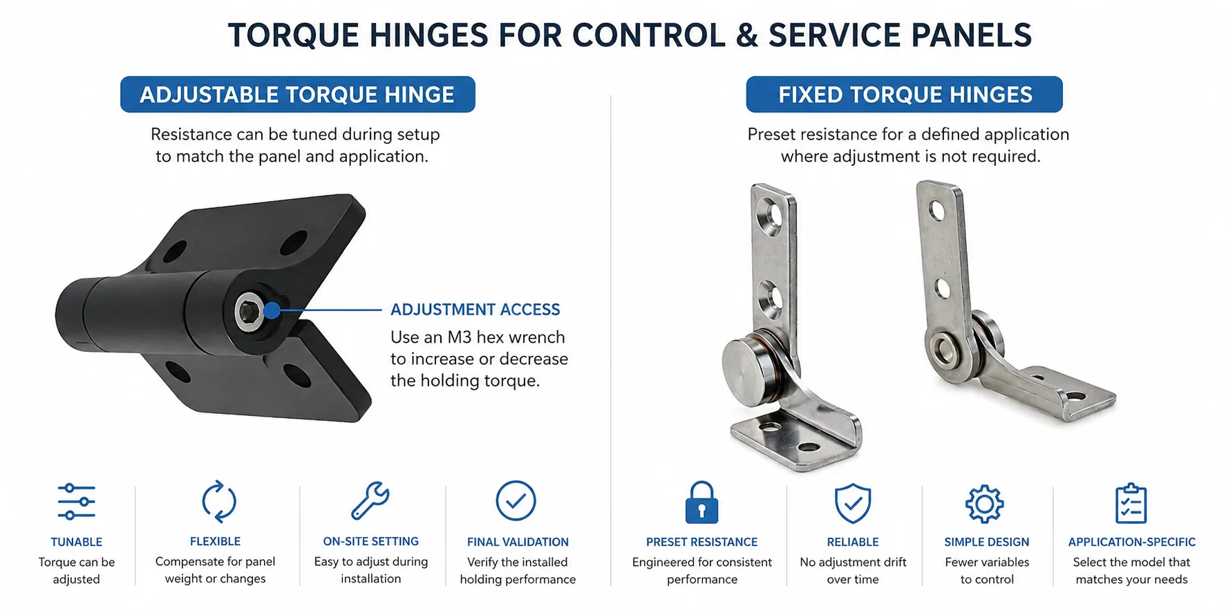
State whether the required resistance is factory-set or adjustable. An adjustable hinge can help during prototype changes, but the project still needs an accessible adjustment point, a locking method, an approved setting record, and a rule for who may change it.
Opening and closing resistance may be similar or intentionally different. Mark the installed orientation and the higher-resistance direction on the assembly drawing. Do not rely only on product-language conventions such as clockwise or counterclockwise without showing the panel movement.
For two hinges, provide quantity, spacing, pair identity, and adjustment method. Adding two nominal torque values is only a preliminary estimate; axis error, unequal settings, and bracket flex can change the complete-panel result.
The unwired panel passed. The finished control panel did not. A hinged faceplate held its operating and service positions on a rigid fixture. After the production harness and grounding strap were installed, the panel slowly returned from the service angle. Increasing hinge resistance stopped the movement, but the operator then needed excessive force for small adjustments. Inspection found that the cable loop was pulling before the intended stop and the thin mounting bracket was twisting during movement. The missing input was not a larger torque number. It was the installed cable path and bracket stiffness.
This is an illustrative engineering scenario, not a customer project record or product test claim.
Touch, Connector, and Tool Loads
The panel does not only resist gravity. The operator and technician apply short-duration forces at different locations, which creates different moments about the hinge axis.
Touchscreens, buttons, and switches. Input near the outer edge can move the panel even when a force closer to the hinge does not. Apply the project-defined interaction at representative locations and observe the panel, faceplate, bracket, and hinge separately. High friction can hide structural flex rather than correct it.
Connector insertion and removal. Plugging or releasing a connector can pull the panel toward the technician or push it into the rear compartment. If the service action requires a rigid reaction point, provide a support or fixture instead of asking friction alone to carry the force.
Rear wiring and tools. A panel may remain stable during normal operation but leave its service position when a terminal clamp is released or a screwdriver is used behind the faceplate. Verify the actual service angle with the intended tool path and component-removal route.
The final opening angle is a separate responsibility. A defined stop should carry abnormal overtravel or impact; position-holding resistance should not be treated as structural stop capacity.
Cable Loops and Grounding Straps
Power, signal, Ethernet, fieldbus, display, and grounding connections cross the moving joint in different ways. Their installed path can change holding behavior even when the cable is not routed through the hinge itself.
- Slack through the full range: the loop must serve the closed, operating, and service positions without becoming taut.
- Defined bend behavior: use the cable supplier or project requirement for bend radius and flexing conditions; do not invent one from the hinge drawing.
- Connector clearance: plugs, backshells, strain reliefs, and ferrules must clear the panel, hinge leaves, cabinet return, and nearby components.
- Grounding strap path: the strap should maintain the required bonding function without pulling the panel sideways or becoming the first travel limit.
- Harness retention: clips and tie points must not create a short rigid segment that concentrates movement at the connector or panel edge.
- Service replacement: the technician must be able to disconnect, support, or remove the panel without damaging the harness.
The cable should not serve as the opening stop. Mark the intended stop position, then verify that every cable and strap still has controlled clearance at that angle.
If wiring must pass through the pivot, transfer bore size, connector passage, shaft cross-section, and sealing decisions to the wire-through torque hinge guide. An external loop and a hollow-shaft joint are different architectures.
Mounting Stiffness and a Common Axis
Torque reaction passes into the hinge leaves, faceplate, bracket, fasteners, and cabinet structure. A thin support can twist while the hinge remains within its own specification. The measured panel movement then combines hinge rotation with structural deflection.
Faceplate and Bracket Deflection
Large screen cutouts, narrow borders, internal studs, and offset brackets can reduce local stiffness. Observe the bracket and faceplate while the panel is touched, repositioned, and held at the service angle. More hinge resistance can increase bracket reaction and make the deflection worse.
Paired-Hinge Alignment
Two hinges can bolt into their holes while their pivot centerlines remain offset or angled. The panel may move smoothly before final tightening and bind afterward. Hole clearance is not an axis-control strategy. The assembly needs a datum or fixture that represents the pivot line.
Raised coating, burrs, uneven washers, local dimpling, insufficient backing, or uneven fastener seating can tilt a hinge leaf and move the pivot line. Show the mounting material, thickness, support, fastener stack, and available assembly access during model review. Complete tightening instructions belong in the released installation work instruction.
What the Installed Symptoms Mean
A failed motion check does not automatically mean that the selected torque value is low. The symptom, angle, direction, and assembly condition help identify the next inspection.
| Observed Behavior | Possible Cause | Evidence to Inspect | Next Engineering Action |
|---|---|---|---|
| Panel slowly leaves the service angle | Insufficient installed holding resistance, cable or strap pull, changing gravity moment, or bracket movement | Drift direction, cable tension, bracket deflection, angle, complete moving mass, and hinge setting | Separate external pull and structural movement from hinge rotation before increasing torque |
| Panel moves when the touchscreen is pressed | Low system resistance, faceplate flex, long touch lever arm, or weak cabinet mounting | Screen location, touch direction, bracket movement, hinge-axis orientation, and panel release behavior | Define the real touch condition and decide whether the hinge or support structure owns stability |
| Movement is smooth in one direction but tight in the other | Directional hinge behavior, axis error, cable routing, latch contact, or uneven adjustment | Opening and closing force by angle, pair settings, gaps, harness movement, and pivot line | Match the observed direction to the approved hinge orientation and remove external interference |
| A tight spot appears near one angle | Axis misalignment, connector interference, cable bending, bracket twist, or stop contact | Panel gap, X1/X2 alignment, rear connector clearance, witness marks, and cable path | Locate the physical contact or forced rotation plane before changing the hinge model |
| The panel holds on the bench but not in the cabinet | Different mounting stiffness, production harness, ground strap, faceplate hardware, or cabinet orientation | Fixture differences, moving BOM, cable installation, bracket support, and hinge spacing | Use the production-intent assembly for acceptance and record the configuration |
| Higher adjustment stops drift but operation becomes difficult | The hinge is compensating for cable pull, support deflection, or an unrealistic hold condition | Operator force, external moments, useful angles, and whether a dedicated stop or support is needed | Correct the system load or change the mechanism architecture rather than continuing to add resistance |
| Panel position changes after final fastening | Leaf movement, uneven seating, bracket distortion, or pivot-axis shift during tightening | Fastener witness marks, coating, leaf contact, backing structure, and before/after movement | Restore flat seating and the common axis, then repeat the installed functional test |
A useful failure record includes the panel angle, movement direction, dwell time, temperature, hinge setting, cable condition, fastener condition, and a video or sequence of photographs. “The hinge is weak” or “the panel is stiff” is not enough to select a corrective action.
Validate the Complete Panel
Bench data screens the hinge. The production-intent cabinet panel decides whether the mechanism works.
- Build the representative assembly. Include the control or HMI faceplate, attached hardware, hinge model and quantity, bracket, fasteners, production cable set, grounding strap, latch or closure, and final stop.
- Inspect the pivot and mounting. Check axis alignment, leaf seating, hinge spacing, faceplate movement, bracket deflection, and changes after final tightening.
- Test the required positions. Evaluate the closed, operating, rear-service, component-removal, and maximum permitted angles that apply to the design.
- Measure intentional movement and release behavior. Record opening and closing force at the actual hand location, then observe drift, creep, spring-back, and bounce after the defined dwell period.
- Apply real interaction loads. Use the intended touchscreen, buttons, switches, connectors, tools, and service actions at representative locations.
- Inspect the harness and final stop. Verify cable loops, strain relief, connector clearance, grounding straps, and the feature that carries the maximum-angle load.
- Repeat and record. Use the same measurements after project-defined conditioning, then tie sample identity, settings, photos, results, deviations, and corrective actions to the released requirement.
Preliminary model review can begin with drawings and estimated data. Sample approval requires a representative mechanism and defined acceptance conditions. Production approval still depends on the controlled panel, harness, mounting, and assembly process.
Application Data for Model Review
Provide the following information before requesting an electrical cabinet torque-hinge recommendation.
| Application Input | Why It Changes the Review | Required Next Action |
|---|---|---|
| Panel type, location, geometry, and orientation | Separates a cabinet-mounted control or service panel from a monitor arm, fixed display, or main cabinet door and defines the motion envelope | Provide an assembly view with the hinge axis and opening direction marked |
| Complete moving weight and center of gravity | Defines the gravity input and mounting reaction at each evaluated position | Include the display, controls, brackets, covers, connectors, and attached hardware and identify the data source |
| Closed, operating, service, removal, and maximum positions | Determines where holding, access, clearance, and stop behavior must be checked | Mark only the positions required by the operating and maintenance procedure |
| Allowable drift and dwell condition | Turns “must hold” into a repeatable acceptance requirement | Define the starting angle, dwell period, direction, and permitted movement |
| Opening, closing, and interaction forces | Prevents the hold target from making repositioning difficult and represents touchscreen, button, connector, and tool disturbances | Define the hand or load point, direction, angle range, speed, and measurement method |
| Cable loop, connectors, strain relief, and grounding strap | External pull can change drift, effort, clearance, and maximum opening behavior | Provide the production harness path and show each moving connection through the required range |
| Hinge quantity, spacing, direction, and adjustment | Affects torque sharing, common-axis behavior, production control, and opening-versus-closing resistance | Show each hinge orientation and state whether resistance is factory-set or adjustable and how the setting is secured |
| Mounting material, bracket, support, and fastener stack | Controls leaf seating, local flex, reaction load, and pivot stability | Provide material, thickness, bracket geometry, backing support, and assembly access |
| Final stop and abnormal-load responsibility | Separates position holding from maximum-angle, overtravel, and impact capacity | Identify the component that carries the final opening load |
| Environment and verification method | Makes prototype, supplier, and production results comparable under the project condition | Define the relevant temperature, vibration, contamination, test assembly, angle, direction, speed, dwell, and record format |
Share the Control-Panel Motion Details
Send the cabinet-mounted control or service-panel drawing, complete moving weight, center of gravity, hinge axis, required positions, acceptable movement and operating force, cable and grounding layout, mounting structure, and stop responsibility. HTAN can use those inputs to review whether an existing torque-hinge configuration or a project-specific sample path deserves evaluation. Final selection remains subject to testing on the intended panel.
FAQs
When does an electrical cabinet panel need torque hinges?
Review torque hinges when a control, HMI, instrument, or service panel must move smoothly and remain at useful operating or maintenance positions without being held by the user. A fixed display, main cabinet door, or panel that only needs one locked service angle may require a different mechanism.
Why can a cabinet control panel drift after the harness is installed?
The production cable loop, grounding strap, connectors, attached hardware, bracket flexibility, and installed hinge alignment can add moments or deflection that were absent from the bench test. Inspect the complete panel and harness before increasing hinge resistance.
Should a cabinet-mounted control panel hold at every angle?
Only when continuous positioning is a real project requirement. Many panels need a closed position, one operating angle, and one rear-service position. Define the required positions and allowable drift instead of assuming that every intermediate angle must be held.
What should be tested on the complete cabinet-mounted panel?
Test the required positions with the production-intent controls, connectors, cables, grounding strap, hinges, mounting brackets, fasteners, and final stop. Record opening and closing effort, drift, spring-back, interaction stability, connector and tool access, mounting movement, and behavior after project-defined conditioning.

 English
  한국어
한국어  Русский
  Español
  Italiano
  Deutsch
  Français
  Português