

Hinge Pin Retention for High-Vibration Equipment
A note such as “secure the hinge pin for vibration” is not a complete engineering specification. It does not identify whether the pin must be removable, what physically blocks axial movement, how much end play is allowed, which dimensions are inspected after assembly, or what vibration evidence is required before production approval.
This guide shows how to specify hinge pin retention for high-vibration equipment in a way that a designer, supplier, inspector, and test engineer can interpret consistently. The objective is not merely to name a retained-pin style. It is to define the retention architecture, critical dimensions, assembly process, inspection method, and acceptance criteria that prevent an unapproved straight pin or incomplete retaining feature from reaching production.
Decision Boundary: Positive Retention or Friction Only?
For high-vibration equipment, begin with a positive axial-retention feature whenever pin escape would affect safety, sealing, latch alignment, equipment protection, or field availability. A positive feature physically blocks the release path through a formed head, crimp, groove and ring, threaded end, cross-pin, captured geometry, or another defined stop.
Gravity, paint, grease, and an unspecified tight fit are not equivalent to positive retention. An interference fit may be a controlled design choice, but its holding force depends on dimensional tolerance, surface condition, assembly process, temperature, corrosion, and wear. It should not be accepted as the only security feature unless the project has validated that exact fit and defined how it will be inspected.
Define the Retention Requirement Before Choosing the Detail
The retention method should be selected from the equipment requirement, not copied from a nearby hinge drawing. Collect the following pin-specific inputs before choosing a formed end, clip, thread, cross-hole, or captured design.
| Required Input | Why It Changes the Retention Detail | Status if Unknown |
|---|---|---|
| Pin must be removable or permanent | Separates formed/captured designs from service-removable retainers | OEM Decision Required |
| Removal frequency | One overhaul in ten years is different from weekly door removal | Project-Specific |
| Installed hinge-axis orientation | Determines whether gravity assists the release direction | Drawing Confirmation Required |
| Vibration and shock directions | Defines whether axial input can occur along the pin | Project-Specific |
| Consequence of partial migration | Determines whether zero visible movement or limited movement is acceptable | Engineering Review Required |
| End-clearance envelope | Controls space for rings, nuts, cotters, tools, and inspection | CAD Review Required |
| External access and tamper risk | May eliminate exposed clips, nuts, or cotter pins | Project-Specific |
| Door removal method | Determines whether the pin, hinge leaves, or complete hinge is serviced | OEM Decision Required |
| Operating contamination | Dirt, ice, chips, or washdown can obstruct small retaining features | Project-Specific |
| Corrosion and temperature environment | Affects pin, retainer, groove, thread, lubricant, and dissimilar-metal choices | Supplier Confirmation Required |
The broad question of whether the equipment needs a heavy-duty weld-on, bolt-on, pivot, bearing, assisted, or other hinge belongs in the heavy-duty hinge selection guide. This page assumes the hinge family has already been selected and addresses only the axial retention of its pin.
Choose Permanent or Service-Removable Retention
The first architecture decision is not “stake or clip.” It is whether removal of the pin is an approved service operation. That decision controls the remaining design choices.
| Service Condition | Recommended Starting Direction | Reason | Required Verification |
|---|---|---|---|
| Pin is never removed during normal service | Staked, swaged, spun, crimped, or internally captured pin | Removes a service step and supports permanent retention | Formed geometry, end play, and destructive or functional retention evidence |
| Pin is removed only during major overhaul | Threaded end, retaining ring, or cross-drilled safety feature | Allows controlled removal without making retention dependent on gravity | Tool access, locking method, replacement-retainer control |
| Pin is removed frequently | Positive removable retainer designed for repeated service | Reduces damage from repeated destructive removal | Repeated assembly test, error-proof installation, spare-retainer plan |
| External pin access is prohibited | Internally captured or non-removable formed pin | Reduces tampering and external snagging | Assembly sequence and hidden-feature inspection |
| Door removal must be tool-free | Evaluate a dedicated lift-off or take-apart architecture | Repeated pin extraction may not be the best service method | Anti-lift, latch, vertical-clearance, and service review |
The industrial removable pin hinges guide covers the broader benefits, procurement logic, and maintenance trade-offs of removable pins. The present article is narrower: once removability has been approved, it defines how the pin is positively retained and inspected.
Select a Retention Architecture That Can Be Inspected
A retention method is only as useful as the evidence that proves it was assembled correctly. Select a design with an inspectable characteristic that remains stable after cycling, vibration, temperature exposure, and service handling.
| Retention Architecture | Positive Feature | Drawing Evidence | Assembly Evidence | Main Risk |
|---|---|---|---|---|
| Staked or peened end | Local displaced material blocks withdrawal | Stake location, retained diameter or profile, allowable end play | Visual standard and post-form measurement | Incomplete displacement, cracking, inconsistent manual forming |
| Swaged or spun head | Formed head exceeds the release diameter | Head diameter D, head height H, pin projection P, end play A | Forming-tool control and dimensional inspection | Under-forming, excessive compression, pin binding |
| Crimped knuckle | Knuckle locally captures the pin | Crimp position C, depth, permitted local deformation | Fixture and go/no-go or visual inspection | Knuckle distortion, increased rotational resistance |
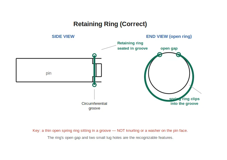
| Retaining ring or E-clip | Ring engages a machined groove | Groove diameter, width, position G, ring specification, end clearance | Ring seating and visual engagement check | Incomplete seating, groove damage, lost ring, poor access |
| Threaded end with nut or cap | Threaded component blocks axial release | Thread, engagement E, nut or cap, locking method, permitted projection | Installation torque or locking confirmation | Loosening, exposed-thread damage, over-tightening |
| Cross-drilled cotter or safety pin | Transverse hardware blocks withdrawal | Cross-hole diameter h, edge distance e, cotter specification, access envelope | Installed orientation and leg-form inspection | Section loss, missing cotter, snagging, incorrect replacement |
| Radial set screw or locking screw | Radial contact prevents axial movement | Thread, point type, engagement, locking method, pin contact location | Torque and thread-lock confirmation | Pin damage, loosening, inconsistent contact force |
| Internally captured pin | Housing or assembled geometry blocks the release path | Section view, assembly order, captured overlap, service restriction | Assembly traceability or functional check | Hidden incomplete assembly, difficult field verification |
| Controlled interference fit | Friction resists axial movement | Pin and bore limits, surface finish, insertion force or displacement | Press-force or installed-position record | Tolerance drift, wear, temperature change, knuckle damage |
Selection rule: Do not choose a retainer only because it is familiar to the supplier. Choose it because the approved service method, available clearance, failure consequence, assembly controls, and inspection evidence support that architecture.
Specify the Pin, Knuckle, and Axial End Play as One System
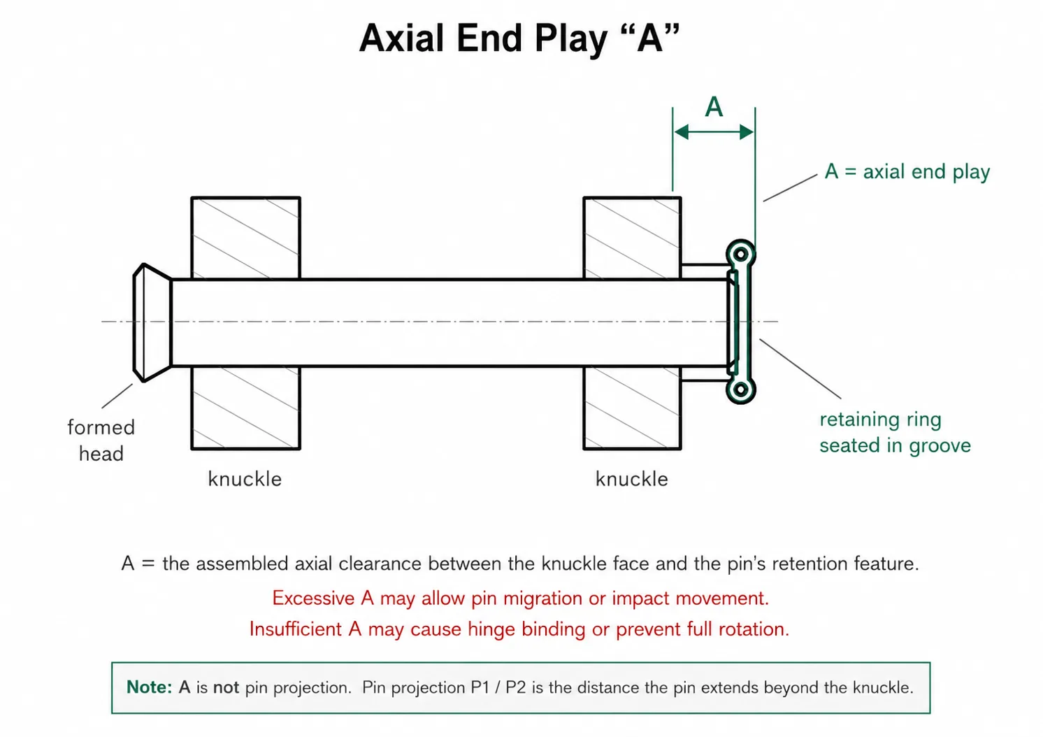
Pin retention cannot be specified independently from the knuckle stack. The pin length, knuckle length, washer or spacer thickness, formed head, groove, nut, and available end clearance combine to determine axial end play.
Excessive end play gives the pin and leaves unnecessary axial travel. Too little end play can clamp the knuckle stack, increase opening force, remove lubricant film, or cause binding when coatings, temperature, or mounting distortion change the stack length. The correct value is project-specific and should be confirmed on the actual hinge construction.
| Drawing Variable | Definition | Why It Must Be Controlled |
|---|---|---|
| d | Pin diameter | Controls fit, retained-end section, ring groove proportions, and bearing interface |
| L | Overall pin length | Controls projection and available retention engagement |
| K | Total assembled knuckle and spacer stack | Forms the base stack for axial-clearance calculation |
| A | Axial end play after retention | Balances free rotation against unnecessary axial movement |
| P1 / P2 | Pin projection at each end | Creates an inspectable assembly and post-test reference |
| D / H | Formed-head diameter and height | Proves the head cannot pass through the release path |
| G | Retaining-groove position | Controls ring engagement and remaining end clearance |
| Wg / dg | Groove width and root diameter | Controls ring fit and the remaining pin section |
| E | Thread engagement length | Controls locking-end strength and serviceability |
| h / e | Cross-hole diameter and edge distance | Controls safety-pin engagement and remaining material |
Specify the dimensions in the assembled condition where necessary. A pin manufactured to the correct length can still produce excessive or negative end play if knuckle length, washers, coating thickness, formed-head displacement, or ring position varies independently.
Add Method-Specific Drawing Notes
A generic note such as “retain pin securely” leaves the supplier to decide the actual design and process. Use notes that identify the approved method and the resulting condition that must be inspected.
For Staked, Peened, Swaged, or Spun Pins
- Identify which pin end or knuckle is formed.
- State whether the pin must rotate or remain stationary after forming.
- Define minimum retained diameter or approved formed profile.
- Define maximum axial end play after forming.
- Define unacceptable cracking, splitting, sharp flash, or knuckle distortion.
- Require a controlled forming fixture or process where repeatability is critical.
For Retaining Rings and Clips
- Specify the exact ring or clip standard and part number.
- Dimension the groove rather than relying only on the retainer catalog.
- Confirm tool access and external clearance.
- Define whether the ring opening has a required orientation.
- Require full seating and a visual or go/no-go acceptance method.
- Define whether the ring is reusable or replaced after removal.
For Threaded Retention
- Specify the thread, engagement, nut or cap, and locking method.
- State whether installation torque or final axial position controls assembly.
- Define whether the threaded element applies preload or only blocks withdrawal.
- Protect exposed threads where impact, corrosion, or contamination is expected.
- Identify replacement locking components after service removal.
For Cross-Drilled Safety Retention
- Dimension cross-hole diameter and edge distance.
- Specify cotter or safety-pin material and size.
- Confirm the installed item cannot interfere with adjacent equipment.
- Define how the cotter legs or locking feature are formed.
- Require a visible installed-condition check.
For Captured or Hidden Pins
- Use a section view to show the physical release barrier.
- Define the assembly sequence that creates capture.
- Identify any hidden retainer that cannot be seen after assembly.
- Specify traceability or a functional check when direct visual inspection is impossible.
Specify Material, Hardness, Finish, and Lubrication at the Retained Interface
The retention feature may introduce a smaller local section, a deformed end, a groove, a thread, or dissimilar-metal contact. The pin material and finish should therefore be reviewed at the retention detail, not only at the bearing surface.
| Specification Field | Retention-Specific Question | Evidence |
|---|---|---|
| Pin material | Can the end be formed without cracking, or can the groove/thread retain strength? | Material designation and supplier process review |
| Hardness | Does hardness support wear resistance but prevent reliable staking or swaging? | Hardness range and forming trial where applicable |
| Surface finish | Will the ring groove, thread, or interference region remain within fit after finishing? | Post-finish dimensional inspection |
| Corrosion protection | Can corrosion seize a removable retainer or reduce the retained section? | Project-specific finish and environmental test |
| Lubricant | Can lubricant reach the retainer or thread and change holding behavior? | Approved lubricant and application boundary |
| Dissimilar metals | Will a stainless ring or pin contact a coated carbon-steel or aluminum hinge in a wet area? | Material compatibility and drainage review |
Do not place the most heavily deformed, grooved, or threaded region at the same location as the highest bearing or bending stress without an engineering review. A retention feature that prevents walkout but weakens the critical load path can exchange one failure mode for another.
Define First-Article and Production Inspection Evidence
The first article should prove the retention design, not merely the overall hinge dimensions. Production inspection should then verify the characteristics that can drift through tool wear, manual forming, incorrect retainer installation, or component substitution.
| Inspection Characteristic | First-Article Evidence | Production Control Direction |
|---|---|---|
| Pin identity | Material, hardness, diameter, length, finish | Lot traceability or incoming inspection |
| Retention method | Drawing section and actual assembled sample | Work instruction and visual standard |
| Formed-end geometry | D, H, profile, cracking and end-play results | Defined sampling and forming-tool checks |
| Ring or clip engagement | Groove dimensions and fully seated retainer | 100% visual or go/no-go check when consequence warrants |
| Threaded retention | Thread engagement, installed position, locking evidence | Torque, witness mark, or locking-process record |
| Cross-drilled retention | Hole position, remaining section, installed safety hardware | Visual installed-condition check |
| Axial end play | Measured A on the assembled hinge | Sampled or 100% inspection based on risk |
| Pin projection | P1 and P2 baseline values | Assembly and post-test comparison |
| Rotational function | No binding, abnormal force, or retainer interference | Functional movement check |
| Retention resistance | Project-specific axial or destructive test where justified | Periodic validation or process capability evidence |
Where direct measurement is difficult, use an approved visual master, profile gauge, go/no-go fixture, witness mark, or documented assembly parameter. “Operator confirms secure” is not an adequate production record unless the secure condition has been defined objectively.
Verify Retention on the Representative Equipment Assembly
A pin-retention feature should be tested in the installed orientation with the representative hinge spacing, door load, mounting stiffness, latch condition, and surrounding clearance. A bare hinge test can verify the retainer itself, but it may not reproduce axial input created by door movement, frame distortion, transport shock, or misalignment.
- Define the sample: identify hinge model, pin and retainer revision, door or equivalent mass, hinge spacing, mounting method, and latch state.
- Record the baseline: measure P1, P2, axial end play A, radial play, leaf position, opening force, and visible retainer condition.
- Use the installed orientation: reproduce the real pin direction and equipment axes.
- Define the vibration input: identify frequency content, axes, acceleration or displacement, duration, and whether the condition represents operation or transport.
- Add shock where required: door slams, road impacts, handling events, and transport shocks may load the retainer differently from steady vibration.
- Inspect during exposure: check witness marks, pin projection, clip seating, thread movement, cotter condition, formed-end damage, and growing end play.
- Repeat the measurements: compare all baseline characteristics after testing.
- Apply written acceptance criteria: define permitted migration, retainer damage, change in end play, functional change, and door-alignment change.
IEC 60068-2-64 provides a broadband random-vibration test method that can reveal accumulated dynamic stress, mechanical weakness, and performance degradation. It does not provide one universal hinge severity, fixture, duration, or pin-migration acceptance limit. Those conditions must come from the relevant equipment specification and actual operating or transportation environment.
Acceptance boundary: “The pin did not fall out” is usually too weak as a pass condition. A sample may still fail when the pin migrates, the retained overlap decreases, the groove or clip deforms, the thread rotates, end play grows, or hinge movement changes.
Composite Engineering Scenario: A Serviceable Generator Door Pin
This is a composite engineering scenario created to explain the selection logic. It is not a customer project record or product test claim.
An enclosure manufacturer uses a removable straight pin because the generator access door must be removed during major engine replacement. The original drawing states the pin diameter and material but does not define axial retention. Production uses a light friction fit, and the pin is installed vertically from the top.
The redesign keeps service removability but replaces the friction-only assumption with a threaded end and locking cap. The drawing now defines pin length L, thread engagement E, allowable projection P, axial end play A, cap material, locking method, service tool access, and replacement of the locking element after removal.
- Requirement: pin removal is permitted only during major overhaul.
- Architecture: positive service-removable threaded retention.
- Drawing control: define thread, engagement, cap, locking method, P, and A.
- First article: verify thread fit, installed cap position, end play, movement, and access.
- Assembly evidence: use an approved installation torque or locking confirmation and a witness mark.
- Validation: test the representative door in its actual orientation under the project vibration and transport profile.
The application-specific relationship between continuous engine vibration, transport, frame movement, heat, gasket compression, and access-door alignment belongs in the generator enclosure hinge guide. The specification task here is limited to making the selected pin-retention method complete and inspectable.
Hinge Pin Retention Specification Checklist
| Specify or Verify | Required Content | Status if Missing |
|---|---|---|
| Service removability | Permanent, overhaul-removable, or frequently removable | OEM Decision Required |
| Retention architecture | Staked, swaged, spun, crimped, ring, thread, cross-pin, set screw, captured, or validated fit | Drawing Revision Required |
| Installed orientation | Pin axis and permitted installation direction | Project-Specific |
| Pin specification | Material, hardness, d, L, straightness, finish | Supplier Confirmation Required |
| Retention dimensions | D, H, G, Wg, dg, E, h, e, or method-specific values | Drawing Revision Required |
| Axial end play | Permitted A in the assembled condition | Engineering Review Required |
| Pin projection | P1 and P2 limits or baseline measurement method | Inspection Requirement |
| Assembly process | Forming, ring installation, tightening, locking, or capture sequence | Supplier Confirmation Required |
| Visual acceptance | Approved formed profile, full clip seating, cotter condition, witness mark | Quality Standard Required |
| Functional acceptance | Free movement without binding or retainer interference | Project-Specific |
| Retention evidence | Dimensional, axial, destructive, or process-based verification | To Be Confirmed |
| Vibration sample | Representative door, hinge spacing, load, latch, mounting, orientation | Test Plan Required |
| Vibration input | Axes, spectrum or frequency range, severity, duration, operational or transport source | Project-Specific |
| Post-test criteria | Migration, end-play growth, retainer damage, functional and alignment limits | Production Approval Required |
| Service instruction | Removal tool, replacement retainer, reassembly and inspection method | Project-Specific |
A preliminary recommendation identifies the likely retention architecture. Engineering review confirms the pin, knuckle, clearance, and service details. Sample approval applies only to the tested configuration. Production approval requires the same pin, retainer, process, dimensions, and inspection evidence to be reproduced.
Final Specification Rule
A complete hinge pin retention specification must answer five questions: Can the pin be removed? What physically blocks axial release? Which dimensions prove that feature exists? How is the assembly inspected? What representative vibration evidence confirms that the retained condition remains acceptable?
For permanent hinges, use a formed or captured feature with measurable post-assembly geometry and controlled end play. For service-removable pins, use a positive, inspectable retainer with defined replacement and reassembly requirements. Do not allow the supplier to substitute a gravity-held or friction-only straight pin unless that exact design has been explicitly approved and validated.
To compare suitable fixed-pin product families, review the heavy-duty hinges range. For a project-specific drawing and pin-retention review, send the hinge drawing, installed orientation, door assembly, service-removal requirement, and vibration profile.
FAQs
What should a hinge pin retention specification include?
It should identify whether the pin is permanent or removable, the positive retention architecture, pin and retainer materials, critical dimensions, assembled axial end play, pin projection, assembly process, inspection method, vibration-test setup, and post-test acceptance criteria. A note that only says secure the pin is not enough.
Is a press-fit hinge pin positive retention?
A press or interference fit resists movement through friction, but it does not create the same physical release barrier as a formed head, ring, nut, cross-pin, or captured feature. It may be acceptable when the fit, surfaces, assembly force, wear, temperature, and vibration behavior are fully controlled and validated. It should not be assumed secure from nominal diameter alone.
How should axial end play be specified on a retained hinge pin?
Specify axial end play in the assembled and retained condition, after coatings, washers, spacers, rings, forming, or threaded components are installed. The allowable range must permit free rotation without giving the pin and leaves unnecessary axial travel. The correct value is project-specific and should be verified on representative samples.
Which hinge pin retention method is best for equipment that needs maintenance access?
There is no universal best method. Retaining rings, threaded ends, cross-drilled safety pins, and other positive removable retainers can support maintenance access. The choice depends on removal frequency, available tool clearance, contamination, tamper risk, locking requirements, and whether replacement retaining hardware can be controlled during service.
What should be checked after vibration testing a retained hinge pin?
Recheck pin projection at both ends, axial end play, retainer seating or formed-end condition, thread or witness-mark movement, radial play, hinge movement, leaf position, and door alignment. The sample can fail even when the pin remains installed if migration, end-play growth, retainer damage, or functional change exceeds the project-specific limit.


 English
  한국어
한국어  Русский
  Español
  Italiano
  Deutsch
  Français
  Português