

Why Die-Cast Hinge Threads Strip During Assembly
Failure Analysis & Assembly Control
Die-cast hinge thread stripping often appears as a simple assembly mistake: the screw turns, the head stops advancing, and the joint will not hold torque. The actual failure may have started much earlier—in the boss geometry, casting porosity, tapped depth, screw length, coating buildup, driver setting, lubricant condition, or decision to use a direct thread where repeated service required an insert.
This guide explains how to diagnose die-cast hinge thread stripping without confusing it with cross-threading, screw damage, blind-hole bottoming, or stripped threads in the cabinet frame. It then shows how engineers and quality teams can correct the drawing, assembly instruction, and sample-validation plan before the same failure reaches production.
Quick Diagnosis: What Usually Strips a Die-Cast Hinge Thread?
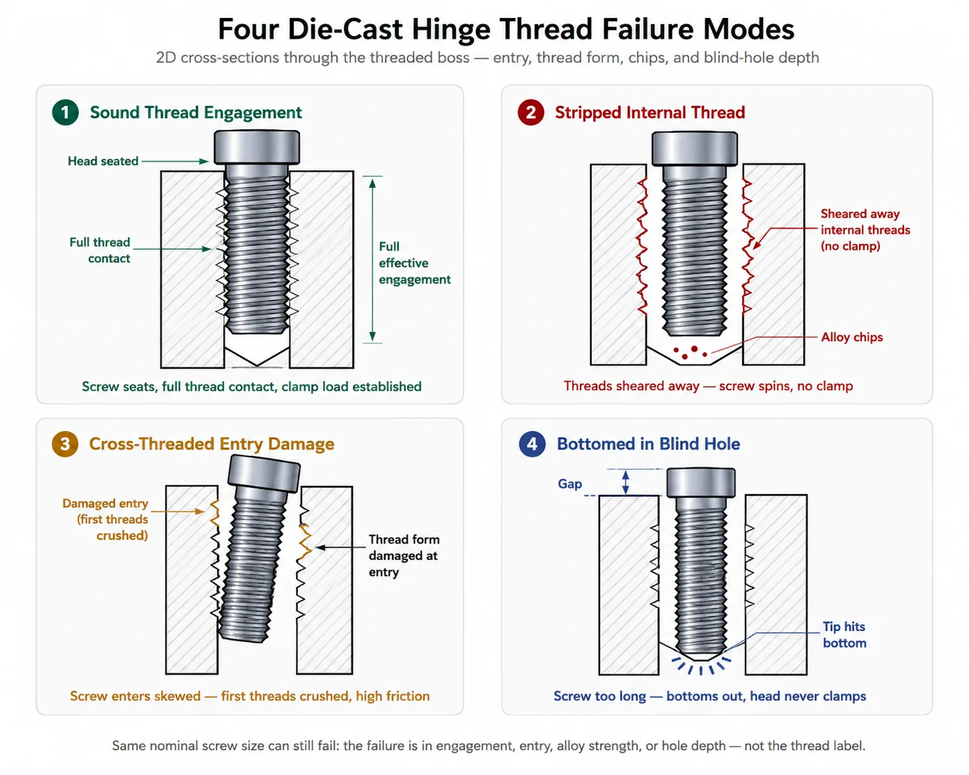
A die-cast hinge thread strips when the internal thread cannot carry the axial load created during tightening. The most common paths are insufficient effective engagement, excessive clamp load from the actual torque-and-friction condition, a weak or poorly supported boss, incomplete or damaged threads, a screw that bottoms before clamping, and repeated assembly that progressively wears the casting.
Do not correct the problem by lowering torque blindly. A lower driver setting may hide the failure while leaving inadequate clamp load. The correct action is to identify whether the joint failed because of geometry, material, manufacturing quality, fastener selection, assembly friction, service frequency, or a combination of those conditions.
Confirm Which Thread or Interface Actually Failed
The screw may spin without building clamp load, but that symptom does not prove that the die-cast internal thread stripped. Preserve the failed components and determine which surface changed.
| Observed Condition | More Likely Failure | Evidence to Check |
|---|---|---|
| Soft casting material is packed into the screw threads | Internal die-cast thread stripping | Sheared thread flanks, damaged first engaged threads, reduced boss material |
| Screw thread crests are flattened or torn while the boss looks intact | External screw-thread damage | Fastener grade, damaged lead thread, incorrect thread form or pitch |
| Screw enters at an angle and binds early | Cross-threading or hole-axis misalignment | Entry damage, asymmetric thread contact, fixture or access angle |
| Screw becomes tight but the hinge remains loose | Blind-hole bottoming | Screw length, usable thread depth, debris or coating at hole bottom |
| Screw will not start by hand | Wrong pitch, damaged lead thread, coating buildup, chips, or incomplete tapping | Thread gauge, matching screw, clean bore inspection |
| Hinge body remains sound but the cabinet panel thread pulls out | Mounting-substrate failure | Panel thickness, backing structure, insert or mounting plate |
| Joint clamps initially but becomes loose after operation | Preload loss, settling, vibration loosening, creep, or bearing-surface embedment | Witness marks, retained torque, surface indentation, joint movement |
Keep the failed screw, hinge, washer, and assembly record together. Cleaning the screw before documenting the transferred casting material can remove the best evidence of thread shear. Record the driver, torque setting, fastener lot, lubricant or threadlocker, screw length, number of previous assemblies, and whether the screw reached the hole bottom.
If the failed thread belongs to the door panel or equipment frame rather than the hinge casting, use the separate guide to hinge mounting plates and frame reinforcement. That page owns substrate pull-out, thin-panel deformation, and backing-plate selection.
Effective Thread Engagement Is Not the Same as Hole Depth
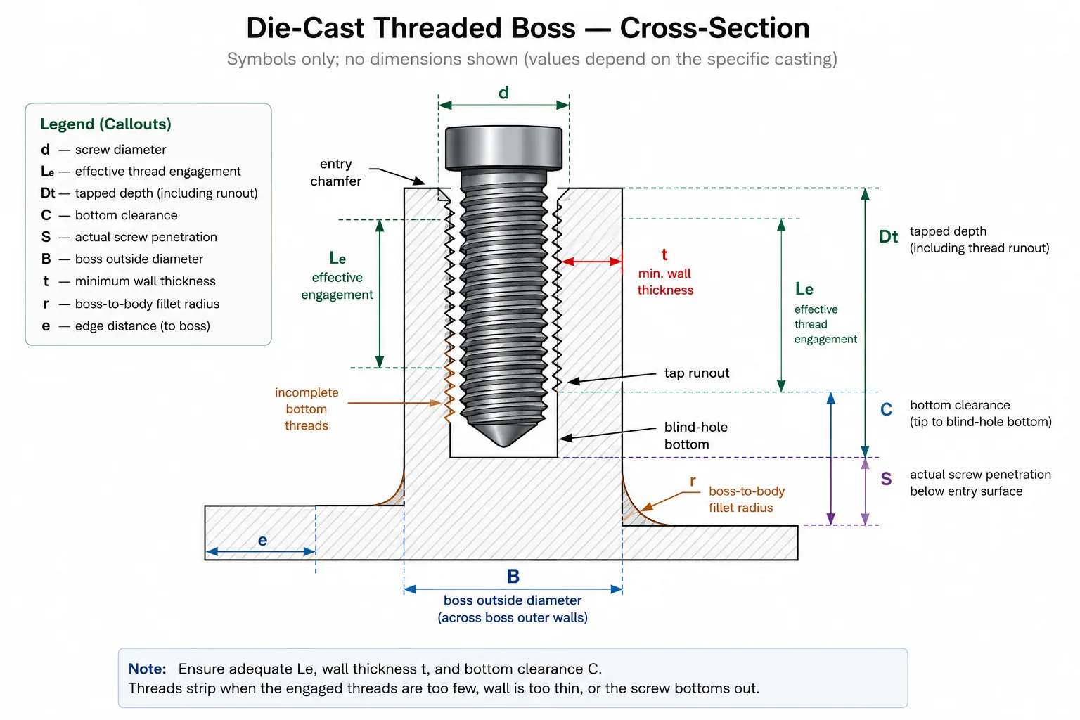
A blind hole may look deep enough on the drawing while providing much less usable engagement. The screw lead, incomplete bottom threads, tap runout, countersink, coating, debris, and required bottom clearance all reduce the length that actually carries load.
For preliminary reasoning, the internal-thread shear area increases with the effective engaged circumference and engagement length. A simplified relationship is:
Screening relationship: Internal-thread stripping resistance generally increases with π × dm × Le × τallow, where dm is an effective thread diameter, Le is effective engagement, and τallow is the project-specific allowable shear stress of the actual casting. This is not a final thread-design equation.
The relationship explains why nominal hole depth alone is insufficient. A longer hole does not improve strength when the additional length contains incomplete threads or the screw does not reach it. Conversely, increasing engagement without increasing boss support may move the failure into the boss wall or surrounding casting.
| Dimension or Condition | What It Controls | Typical Specification Error |
|---|---|---|
| Nominal tapped depth Dt | Total depth called out for the tapping operation | Assumed to equal full usable engagement |
| Effective engagement Le | Length of complete internal and external thread contact | Not calculated after entry, runout, and bottom clearance |
| Screw engagement Ls | Length of screw actually entering complete internal threads | Short screw uses only the first few threads |
| Bottom clearance C | Prevents screw bottoming before clamp load develops | No allowance for chip, coating, or tip geometry |
| Entry chamfer or countersink | Supports assembly and removes a sharp lead edge | Oversized entry removes too many load-bearing threads |
| Thread runout R | Transition to incomplete bottom threads | Included as usable engagement |
Assembly Torque Creates Clamp Load Through Friction
The driver applies torque, but the thread fails from the axial and local contact loads produced by that torque. Only part of the applied torque becomes useful preload. The rest is consumed by friction in the threads and under the screw head or washer.
A common preliminary relationship is:
Preliminary torque relationship: F ≈ T / (K × d), where F is estimated preload, T is installation torque, d is nominal screw diameter, and K is a friction-related factor. The value of K is not universal and changes with finish, lubricant, threadlocker, washer, contamination, and surface condition.
This is why a torque that worked with a dry zinc-plated screw can overload the same cast thread when the fastener is lubricated or supplied with a different coating. Lower friction can create higher preload at the same indicated torque. Higher friction can produce the opposite problem: the driver reaches its torque setting before adequate clamp load develops.
ISO 16047 specifies conditions for torque/clamp-force testing of threaded fasteners and related parts. It helps define how torque and clamp force are measured, but it does not provide one correct installation torque for a die-cast hinge boss, define acceptable casting porosity, or prove that a specific hinge joint is suitable for production. Those limits remain project-specific.
| Assembly Change | Possible Effect at the Same Driver Setting | Required Response |
|---|---|---|
| Lubricated screw replaces dry screw | Higher preload and increased stripping risk | Revalidate torque and clamp condition |
| Threadlocker added | Friction and prevailing torque change | Test the exact product and cure condition |
| Washer removed or changed | Bearing friction and surface pressure change | Review both preload and hinge-seat damage |
| Fastener coating changes | Torque-tension relationship changes | Control approved fastener finish |
| Impact driver replaces controlled screwdriver | Dynamic peaks and overshoot may increase | Use a validated tool and rundown method |
| Automatic driver speed increases | Heat, seating behavior, and shutoff overshoot may change | Validate speed and tool capability |
Boss Geometry Determines Whether the Thread Is Supported
A thread may have adequate engagement on paper and still strip because the surrounding boss cannot support it. The boss outside diameter, wall thickness, fillet, distance to a free edge, rib connection, and local casting section determine how the thread load moves into the hinge body.
Common geometry failures include a narrow boss that expands or cracks during tightening, a thread placed too close to an edge, a sharp boss-to-body transition, a deep thread surrounded by a thin wall, or a boss connected to the hinge leaf through an unsupported flat section. Countersunk screw seats can add another failure path because the conical head creates radial expansion as well as axial clamp load.
| Boss Feature | Failure Risk When Inadequate | Design Review |
|---|---|---|
| Outside diameter B | Boss expansion, splitting, or local shear | Review remaining material around the thread root |
| Wall thickness t | Cracking or distortion before full clamp load | Check the thinnest local section, not only nominal boss diameter |
| Fillet radius r | High stress at the boss-to-body transition | Use a castable transition and verify tool access |
| Edge distance e | Breakout toward a nearby edge or pocket | Review the actual load direction and porosity risk |
| Rib support | Boss tilting or bending under screw preload | Connect the boss to a structural section without creating thick hot spots |
| Countersink geometry | Radial spreading and local crushing | Verify head angle, seat contact, depth, and boss support |
| Blind-hole base thickness | Bottom cracking or breakout | Maintain project-specific material below the drilled or tapped hole |
The correct boss design is material-specific. Zinc and aluminum castings differ in alloy properties, casting behavior, compact-detail capability, temperature response, and the geometry needed around threads. Those broader trade-offs belong in the zinc alloy vs aluminum alloy die-cast hinge guide.
Casting and Tapping Defects Can Reduce the Available Thread
The drawing may be correct while the produced boss is not. Die-cast pores, cold shuts, shrinkage-related voids, oxide films, local inclusions, drill wander, worn taps, incorrect tap depth, chips, and damaged lead threads can reduce the amount of sound material carrying the screw load.
Porosity Near the Thread Root
A visible external surface does not reveal the internal condition around the tapped hole. Porosity intersecting the thread root reduces the continuous shear path and can produce an irregular failure surface. When failures cluster by cavity, batch, boss location, or machining lot, sectioning or another project-approved internal inspection method may be justified.
Drilling and Tapping Alignment
A hole drilled off-axis creates uneven thread depth around the circumference. The thread gauge may enter, yet the thinnest side of the boss carries less material. Misalignment can also cause the mounting screw to enter at an angle when the hinge is assembled against a rigid mating part.
Incomplete Threads and Tap Wear
Tap wear can change thread form, surface quality, and effective size. A damaged entry can encourage cross-threading, while chips left in a blind hole can create false seating or bottoming. The supplier should define how thread size, usable depth, cleanliness, and tap condition are controlled for the critical boss.
The broader relationship between casting, trimming, machining, component preparation, and controlled assembly is covered in how torque hinges are made. This article remains limited to the threaded feature and its assembly failure.
Repeated Assembly Changes the Correct Design Choice
A direct tapped casting may perform adequately in a controlled one-time factory assembly and fail after repeated removal. Every service cycle can damage the lead thread, transfer debris, wear the flanks, change lubrication, or allow the screw to start off-axis.
| Service Condition | Preferred Starting Direction | Validation Needed |
|---|---|---|
| One controlled factory installation | Direct tapped casting may be acceptable | Torque margin, clamp function, and destructive sample evidence |
| Occasional planned maintenance | Direct thread or insert depending on boss margin and access | Defined repeated-assembly test using the real screw and tool |
| Frequent field removal | Consider steel, stainless, or brass insert | Cycle the insert, screw, locking method, and service procedure |
| High clamp load in a compact boss | Insert, larger boss, revised fastener, or through-bolt | Joint-level clamp and failure testing |
| High sustained temperature | Review direct-thread relaxation and insert compatibility | Clamp retention after project temperature exposure |
| Uncontrolled field tools | Reduce reliance on installer feel; use robust retention architecture | Service tool, torque control, and misuse review |
An insert is not an automatic cure. The casting must still retain the insert, and the insertion process can split or distort a weak boss. Press-in, self-tapping, cast-in, and post-installed threaded inserts create different radial loads, installation requirements, and service behavior. The insert type, installation depth, pull-out or torque resistance, and replacement policy must be project-specific.
Correct the Drawing and Assembly Instruction Together
A drawing that states only “M5 tapped hole” leaves several failure-critical conditions undefined. The product drawing, fastener specification, and assembly instruction should agree on the same joint.
| Control Field | What to Specify | Why It Matters |
|---|---|---|
| Internal thread | Size, pitch, class or tolerance, and full-thread requirement | Prevents incorrect or incomplete thread form |
| Effective engagement | Minimum Le with the approved screw | Defines the actual load-carrying length |
| Usable hole depth | Complete-thread depth plus bottom clearance | Prevents bottoming and false torque |
| Boss geometry | B, t, r, e, local ribs, and minimum base thickness | Supports the thread and transfers preload into the hinge body |
| Fastener | Material, property class where applicable, finish, point, and approved source | Controls strength, friction, and thread compatibility |
| Washer or bearing interface | Washer type, head style, seating diameter, and permitted countersink | Controls bearing friction and local pressure |
| Lubricant or threadlocker | Exact product, application location, quantity, and cure condition | Controls friction and assembly repeatability |
| Installation torque | Project-approved value, tool tolerance, speed, and rundown method | Controls preload and overshoot |
| Service reuse | Permitted assembly count and replacement requirements | Prevents unvalidated repeated use |
| Insert when used | Type, material, installation process, depth, and acceptance | Prevents unapproved insert substitution |
Do not copy a torque value from a generic chart without confirming the internal-thread material, boss geometry, screw finish, lubricant, washer, and required clamp load. Generic charts often assume a steel nut or a different friction condition. The die-cast internal thread may be the weakest member of the joint.
Validate the Revised Joint With the Real Assembly Conditions
A thread gauge confirms thread size. It does not prove that the boss will survive the production driver, create the required clamp load, tolerate repeated service, or remain sound after temperature exposure. Validation should reproduce the actual casting, finish, fastener, washer, chemical condition, tool, access angle, and mating component.
- Identify the exact sample: record hinge model, casting alloy, cavity or lot where available, finish, machining revision, insert condition, and thread specification.
- Verify the geometry: measure usable thread depth, effective screw engagement, boss dimensions, bottom clearance, screw length, and seating condition.
- Verify the thread: use the approved thread gauge and inspect the lead, chips, coating, and blind-hole bottom.
- Reproduce assembly: use the production screw, washer, lubricant or threadlocker, driver, speed, fixture, and access angle.
- Record torque behavior: capture rundown and shutoff information where the equipment permits; investigate abnormal early torque rise or overshoot.
- Check clamp function: verify that the hinge seats fully and the required joint function is achieved without local boss damage.
- Establish margin: use a project-approved destructive or proof method on separate samples to understand failure mode and available margin.
- Repeat assembly when required: test the approved number of removal and reinstallation cycles with the real service procedure.
- Inspect the proof-tested boss: document whether failure occurred by internal-thread shear, boss cracking, insert pull-out, screw failure, or bearing-seat damage.
- Retest after relevant exposure: include temperature, corrosion, cleaning, or vibration only when it can change the actual joint.
Validation boundary: A sample that survives one installation is not automatically approved for repeated field service. A sample that passes a plug gauge is not automatically approved for the specified clamp load. Each test answers a different question.
Composite Engineering Scenario: The Torque Setting Was Not the Only Problem
This is a composite engineering scenario created to explain the selection logic. It is not a customer project record or product test claim.
An OEM installs a zinc-alloy die-cast equipment hinge using two machine screws. Several hinges assemble correctly, while others strip before the driver reaches its programmed shutoff. The immediate response is to reduce torque.
Inspection shows four interacting conditions. The approved screw is longer than the earlier prototype screw. Chips at the blind-hole bottom reduce available clearance. The useful full-thread depth is shorter than the nominal tapped depth. One boss also has a thin local wall near a casting pocket. Reducing torque allows assembly, but the hinge does not consistently seat against the frame.
- Separate bottoming from stripping: compare screw length with measured usable depth and inspect the screw tip.
- Correct effective engagement: define full-thread depth, bottom clearance, and approved screw length.
- Review boss support: increase local material or move the pocket where the section is inadequate.
- Control the assembly condition: specify screw finish, tool, speed, and approved torque based on the revised joint.
- Validate clamp function and failure mode: confirm full seating, required joint function, and project-specific margin on separate samples.
The final correction is not simply “use less torque.” It removes false torque from bottoming, restores usable engagement, strengthens the local load path, and then establishes an assembly setting for the real joint.
Die-Cast Hinge Thread-Stripping Checklist
| Verify | Required Evidence | Status if Missing |
|---|---|---|
| Failed interface | Internal casting thread, screw thread, insert, panel thread, or blind-hole bottom | Failure Analysis Required |
| Casting alloy and condition | Exact alloy, finish, lot or cavity where available | Supplier Confirmation Required |
| Internal thread | Size, pitch, tolerance, gauge result, lead condition | Drawing or Inspection Update Required |
| Effective engagement Le | Measured complete-thread contact with approved screw | Engineering Review Required |
| Usable blind-hole depth | Complete threads, runout, bottom clearance, cleanliness | Inspection Required |
| Screw specification | Length, material, property class where applicable, point, finish, approved source | Supplier Confirmation Required |
| Boss geometry | B, t, r, e, base thickness, rib and pocket relationship | Drawing Review Required |
| Casting soundness | Section, lot pattern, or approved internal inspection where justified | Project-Specific |
| Assembly chemistry | Dry, lubricant, threadlocker, quantity, and cure condition | Process Confirmation Required |
| Driver condition | Tool type, setting, tolerance, speed, bit, access angle | Work Instruction Required |
| Seating condition | Hinge fully seated before shutoff without screw bottoming | Functional Check Required |
| Installation torque | Project-approved value based on actual joint testing | To Be Confirmed |
| Repeated service | Permitted assembly count and replacement policy | Project-Specific |
| Insert specification | Type, material, installation, depth, retention and service method | Required When Used |
| Validation result | Clamp function, margin, failure mode, and sample traceability | Sample Approval Required |
A preliminary recommendation can identify likely causes and a preferred correction. Engineering review must confirm the joint geometry and load path. Sample approval applies to the tested casting, screw, finish, chemical condition, and assembly process. Production approval requires those same controlled inputs to be reproduced.
Final Rule: Do Not Treat Thread Stripping as a Torque-Only Problem
Die-cast hinge thread stripping is a joint-system failure. The internal thread, boss, casting, screw, washer, lubricant, tool, mating surface, and service cycle all influence the result. Lowering torque without confirming clamp function can replace an obvious assembly failure with a loose hinge in service.
Confirm the failed interface first. Then define effective engagement rather than nominal hole depth, check boss support and casting quality, control the exact fastener and friction condition, and validate the production assembly. Use a threaded insert or revised mounting architecture when the direct casting cannot provide reliable margin or repeated service life.
For a project-specific review, send the hinge drawing, casting alloy, boss section, screw specification, assembly torque, lubricant or threadlocker, failure photographs, and failed samples.
FAQs
Why does a screw spin in a die-cast hinge without tightening?
The internal casting thread may have stripped, but the screw can also be bottomed in a blind hole, cross-threaded, mismatched in pitch, blocked by chips or coating, or damaged itself. Inspect the screw, transferred casting material, usable hole depth, entry condition, and mating thread before identifying the failure.
Can lowering assembly torque prevent die-cast thread stripping?
It can reduce the immediate load, but it may also leave inadequate clamp force. The correct torque depends on the actual casting, engagement, boss geometry, screw finish, washer, lubricant or threadlocker, driver, and required joint function. Correct the failure mechanism and then validate the revised torque on the real assembly.
How much thread engagement does a die-cast hinge need?
There is no universal engagement ratio for every zinc or aluminum die-cast hinge. Required effective engagement depends on the exact alloy, sound casting material, thread size, boss geometry, screw strength, clamp load, friction condition, temperature, and service cycles. Use the complete engaged length, not nominal blind-hole depth, and validate the actual joint.
When should a die-cast hinge use a threaded insert?
Consider an insert when the mounting screw must be removed repeatedly, the direct casting has limited stripping margin, the boss is compact, the clamp load is high, or the field assembly process cannot reliably protect the soft internal thread. The casting must still be designed and tested to retain the selected insert.
Does a GO/NO-GO thread gauge prove the hinge thread is strong enough?
No. A thread gauge checks specified thread size or acceptance characteristics. It does not prove adequate effective engagement, boss wall thickness, casting soundness, clamp load, assembly margin, repeated service life, or resistance to the exact production driver and friction condition. Those require joint-level validation.

 English
  한국어
한국어  Русский
  Español
  Italiano
  Deutsch
  Français
  Português