

How Torque Hinges Are Made: Die-Casting & Assembly
Understanding how torque hinges are made is essential when an OEM needs more than a part that simply rotates. A torque hinge must create controlled resistance, hold a panel at the required angle, feel consistent from unit to unit, and retain usable behavior after repeated movement. Those outcomes are not produced by the housing alone. They come from the interaction between the cast or machined body, shaft geometry, friction surfaces, spring or washer preload, assembly sequence, lubrication condition, and final calibration.
This guide follows that manufacturing chain from die-casting through precision assembly and torque verification. It is written for engineers, quality teams, and buyers who need to determine whether a supplier can reproduce the same mechanical behavior in samples and production—not merely make two hinges that look alike.
Quick Answer: How Are Torque Hinges Made?
Many compact torque hinges are made by die-casting a zinc-alloy or aluminum-alloy housing, trimming and machining its critical interfaces, preparing the shaft and friction components, assembling those components in a controlled order, applying a specified preload, securing the assembly axially, and measuring the resulting torque behavior. Depending on the design, the friction system may use metal or polymer contact surfaces, spring washers, friction discs, wrapped elements, or other proprietary structures. The manufacturing objective is not only dimensional fit. It is repeatable breakaway torque, running torque, directionality, smoothness, and holding behavior within the project-specific acceptance limits.
Why Torque Hinges Need a Different Manufacturing Route
A conventional butt hinge can perform its basic function when two leaves rotate around a sufficiently aligned pin. A torque hinge has an additional job: it must deliberately resist that rotation. The housing and shaft therefore become parts of a friction-control system rather than only a pivot structure.
Small variations that may be tolerable in a free-swinging hinge can become visible in a torque hinge. A change in shaft diameter, friction-surface finish, washer thickness, spring preload, lubricant amount, or assembly compression can alter the user force and holding torque. The same external dimensions do not guarantee the same mechanical behavior.
| Manufacturing Variable | Torque-Hinge Effect | Possible User-Level Symptom |
|---|---|---|
| Housing bore or shaft fit | Changes alignment and contact behavior | Binding, noise, uneven rotation |
| Friction-surface condition | Changes coefficient of friction and wear behavior | Torque variation, stick-slip |
| Spring or washer preload | Changes normal force in the friction stack | Too loose, too stiff, inconsistent hold |
| Lubricant type or quantity | Changes running feel and temperature response | Heavy startup, torque fade, contamination |
| Assembly compression | Changes total friction-pack loading | Unit-to-unit variation |
| Axial retention | Controls stack position during cycling | End play, loosening, torque drift |
This manufacturing sensitivity is why torque hinges are treated differently from sheet-metal hinges on the factory floor: quality is won or lost primarily in precision interfaces, friction-component consistency, assembly, and calibration. It is also why hinges that must work as a set are often screened as matched pairs rather than picked at random.
Manufacturing Architecture: What Is Actually Being Made?
There is no single universal torque-hinge construction. Before evaluating a process, the buyer must understand which components in the proposed design generate torque and which components only provide structure or mounting.
| Component | Primary Function | Manufacturing Concern |
|---|---|---|
| Housing or body | Supports the mechanism and mounting geometry | Porosity, dimensional stability, machined datums |
| Shaft or pivot | Transfers rotation through the friction mechanism | Diameter, straightness, hardness, surface finish |
| Friction discs or contact elements | Generate controlled rotational resistance | Thickness, flatness, material lot, surface condition |
| Spring washers or preload element | Apply normal force to friction interfaces | Load-deflection consistency, stack orientation |
| Spacer, sleeve, or bushing | Controls position, alignment, and wear surface | Length, concentricity, material compatibility |
| Retainer, rivet, nut, or formed end | Maintains axial compression and prevents separation | Retention force, end play, permanent deformation |
| Adjustment screw, when used | Changes preload after assembly | Thread fit, locking method, usable adjustment range |
A supplier should be able to identify the torque-generating interface in the design. Statements such as “friction inside” are not enough for an engineering review. The relevant question is which surfaces move against each other, what creates the contact force, and which dimensions control that force.
Stage 1: Die-Casting the Torque Hinge Housing
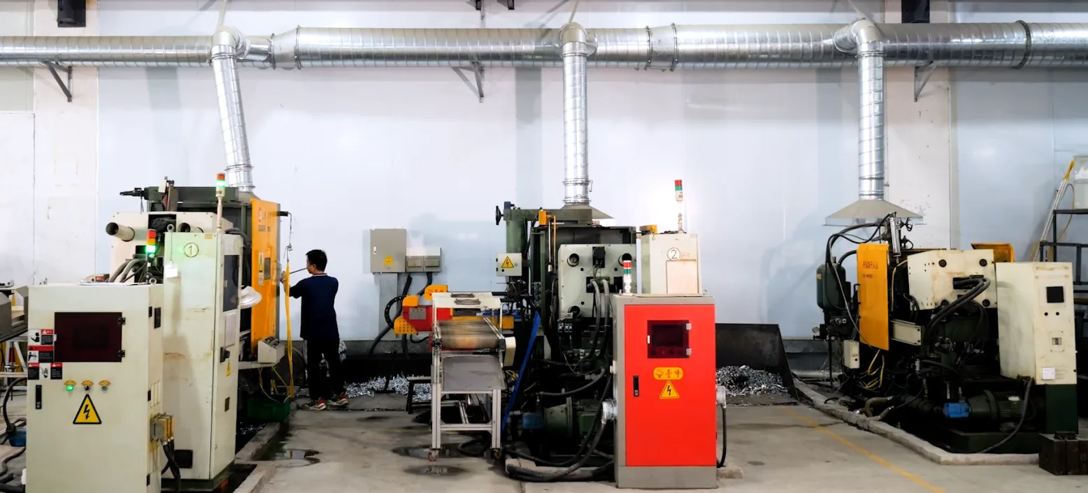
Die-casting is commonly used when a torque hinge needs a compact body with integrated mounting features, ribs, pockets, bosses, stops, or cosmetic surfaces. Zinc alloys are often selected for detailed small parts and good castability; aluminum alloys may be used where lower mass or a different strength-to-weight balance is required. The actual alloy must be confirmed from the drawing or supplier material specification.
Molten alloy is injected into a steel die under pressure. The die forms the external shape, internal cavities, bosses, and near-net mounting geometry. After solidification, ejector pins release the casting. Gates, runners, overflow material, and flash are removed before the housing proceeds to secondary operations.
What the Die Must Control
- Material flow: the cavity must fill before premature solidification creates incomplete features.
- Venting and overflow: trapped air and displaced metal need controlled escape paths.
- Shrinkage allowance: the tool must account for material contraction after injection.
- Draft and ejection: the housing must release without distortion or unacceptable drag marks.
- Machining allowance: critical bores and reference faces need enough stock for stable secondary machining.
Casting Defects That Matter to a Torque Hinge
| Possible Casting Condition | Why It Matters Here | Verification Method |
|---|---|---|
| Porosity near a machined bore | May open during machining or weaken a loaded boss | Section review, X-ray when project-required, machining inspection |
| Incomplete fill | May reduce feature definition or wall section | Visual and dimensional inspection |
| Cold shut or flow line | May indicate poor fusion at a critical feature | Visual review and project-specific acceptance criteria |
| Excess flash | Can interfere with seating, assembly, or finishing | Visual inspection and flash limit |
| Ejector distortion | Can move mounting faces or internal alignment | Flatness and datum inspection |
Engineering boundary: A smooth outer casting does not prove that the internal bore, wall section, or loaded boss is acceptable. Cosmetic appearance and structural soundness are separate inspection questions.
Stage 2: Trimming, Deburring, and Preparing the Casting
After ejection, the housing goes through gate removal, flash control, and edge breaking before precision assembly. Those are standard casting-cleanup steps — but for a torque hinge, one of them carries unusual weight: removing every loose particle. A small fragment left in a cavity can later migrate into the friction interface and change the hinge feel, so cleanliness here is a torque-control concern, not just a cosmetic one.
Cleaning must remove chips, abrasive residue, casting-release material, and oil before the friction components are installed, because any of these can contaminate the contact surfaces that generate torque. Deburring around shaft passages and adjustment openings also affects whether internal components seat against their intended surfaces during assembly.
The detailed relationship between edge preparation, cleaning, and coating performance belongs to the separate guide on hinge surface preparation before finishing. For torque-hinge assembly, the immediate concern is contamination and seating accuracy inside the mechanism.
Stage 3: Machining the Critical Interfaces
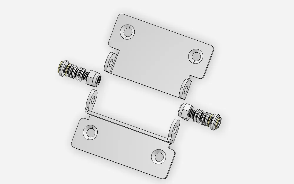
Die-casting provides the near-net housing shape, but the interfaces that govern alignment and friction behavior may still require drilling, reaming, boring, facing, tapping, or CNC machining. The drawing should distinguish cast dimensions from machined dimensions instead of applying one tolerance philosophy to the entire part.
| Critical Feature | Why It Matters | Typical Drawing Control |
|---|---|---|
| Shaft or bearing bore | Controls alignment, clearance, and contact pattern | Diameter, position, cylindricity or runout when required |
| Friction-stack seat | Controls preload distribution and element flatness | Depth, flatness, perpendicularity |
| Mounting face | Controls how the hinge aligns in the product | Flatness and relation to pivot axis |
| Threaded adjustment feature | Controls preload adjustment and locking | Thread specification, engagement, positional tolerance |
| Mechanical stop | Controls travel limit and contact location | Angular position and local strength |
ISO 2768-1 can simplify drawings by defining general tolerances for linear and angular dimensions without individual tolerance indications. It does not decide the correct fit for a torque-hinge shaft, the acceptable bore geometry, the required preload stack, or the torque acceptance range. Those function-critical features still need individual engineering tolerances and project-specific verification.
Buyer check: Ask which dimensions are produced directly by the die and which are finish-machined. A supplier that cannot separate those two groups may not have identified the features that control torque-hinge behavior.
Stage 4: Preparing the Shaft and Friction Components
The housing carries the mechanism, but the torque is generated at the friction interfaces. The shaft, sleeve, discs, washers, polymer elements, or wrapped friction components must therefore be controlled as a functional set rather than treated as unrelated purchased pieces.
Shaft Requirements
The shaft may require turning, grinding, heat treatment, coating, polishing, or controlled texturing depending on the design. Diameter and straightness affect fit; surface finish affects friction and wear; hardness affects whether the contact surface changes after cycling. A visually polished shaft is not automatically correct if its diameter or surface condition falls outside the design requirement.
Friction Elements and Preload Parts
Friction discs and polymer elements may be stamped, molded, machined, or purchased to specification. Spring washers and wave washers must be installed in the correct orientation and stack sequence. Their free height alone does not prove that they generate the required load; the relevant characteristic is the load-deflection behavior at the installed compression.
| Input | What Must Be Controlled | Status if Data Are Missing |
|---|---|---|
| Shaft material and hardness | Wear resistance and friction-surface stability | Supplier Confirmation Required |
| Shaft diameter and finish | Fit, friction, and running consistency | Project-Specific |
| Friction-element material | Coefficient of friction, wear, temperature response | Supplier Confirmation Required |
| Element thickness and flatness | Total stack height and pressure distribution | Project-Specific |
| Spring load at installed height | Normal force applied to friction interfaces | To Be Confirmed |
| Lubricant or dry-friction condition | Torque, noise, wear, contamination sensitivity | Supplier Confirmation Required |
Stage 5: Assembly Order and Preload Control
Torque-hinge assembly is not only the act of putting components together. It is the stage where dimensional variation becomes actual contact force. The order of washers and friction elements, their orientation, the cleanliness of the contact surfaces, and the final axial compression all affect the result.
- Confirm component identity: verify housing, shaft, friction elements, preload components, spacers, and retainers against the approved bill of materials.
- Clean the torque-generating interfaces: remove chips, abrasive particles, excess oil, and handling contamination according to the defined process.
- Load the stack in the approved sequence: maintain orientation for directional components, spring washers, and one-way mechanisms.
- Insert and align the shaft: avoid forcing misaligned components through the housing.
- Apply the specified compression or setting: use a controlled dimension, force, forming operation, or adjustment method.
- Secure axial retention: verify rivet forming, staking, nut locking, clip engagement, or other retention method.
- Check end play and free movement: confirm the stack is retained without unintended binding.
Some designs establish preload by a fixed riveted or staked dimension. Others use a nut, screw, wave spring, disc-spring stack, or adjustable mechanism. The supplier should identify which assembly characteristic is controlled directly: installed stack height, forming displacement, applied force, tightening torque, torque output, or a combination of these.
Manufacturing evidence: “Assembled by experienced workers” is not a control method. The relevant evidence is the assembly fixture, controlled setting, work instruction, component traceability, and recorded torque result.
Stage 6: Torque Calibration Is More Than One Number
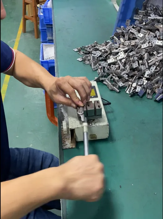
After assembly, the hinge must be measured as a motion-control component. A single peak reading taken by hand does not describe how the hinge behaves through its travel. The test method should define angle range, rotational speed, direction, number of conditioning cycles, fixture alignment, temperature, and where the reported values are taken.
| Measured Characteristic | What It Means | Why It Matters |
|---|---|---|
| Breakaway torque | Torque required to initiate motion | Controls initial user effort and stick-slip perception |
| Running torque | Torque during continued rotation | Controls movement feel and holding resistance |
| Torque-angle curve | Torque measured across the travel range | Reveals peaks, drops, and angle-dependent variation |
| Opening/closing difference | Difference between rotational directions | Identifies hysteresis or intentional one-way behavior |
| Repeatability | Variation across repeated cycles on one unit | Shows short-term stability |
| Unit-to-unit variation | Variation among multiple samples | Shows manufacturing consistency |
| Pair balance, when required | Difference between two hinges used in one assembly | Helps prevent uneven motion in dual-hinge systems |
The acceptance range is project-specific. It may be supplied by the OEM, recommended preliminarily by the supplier, or developed through prototype testing. A preliminary recommendation is not production approval. Engineering review checks whether the proposed mechanism is plausible; sample approval confirms the tested samples; production approval requires evidence that the controlled process can reproduce the approved behavior.
Torque sizing based on panel weight and center of gravity belongs in the separate torque hinge selection guide. This manufacturing page assumes the project torque requirement has already been defined and focuses on whether the process can reproduce it.
How Manufacturing Errors Appear in the Finished Hinge
Scope note: The issues below are deviations introduced during manufacturing—they show up on first samples or across a production batch. They are different from torque loss that develops during service life, which belongs in separate torque-decay and sagging analysis.
| Observed Problem | Possible Manufacturing Source | Evidence to Check |
|---|---|---|
| High breakaway, normal running torque | Surface condition, lubricant distribution, static adhesion | Torque curve and friction-interface process |
| Torque too low on all samples | Insufficient preload, wrong friction material, excess lubrication | Stack record, material identity, assembly setting |
| Large unit-to-unit variation | Component thickness spread, uncontrolled compression, manual adjustment variation | Component inspection and assembly records |
| Torque changes sharply with angle | Misalignment, uneven seat, geometry interference | Torque-angle curve and dimensional inspection |
| Noise or stick-slip | Contamination, surface finish, dry contact, misalignment | Cleanliness record and interface inspection |
| Axial play after cycling | Retention deformation or stack settling | End-play measurements before and after cycling |
| Left/right system imbalance | Torque variation or directional assembly error | Individual curves and assembly identification |
These links are diagnostic, not automatic conclusions. The same symptom can have more than one cause. A useful supplier response connects the symptom to measurable evidence rather than replacing analysis with “normal tolerance.”
Composite Engineering Scenario: A Display Hinge With Inconsistent Feel
This is a composite engineering scenario created to explain the manufacturing logic. It is not a customer project record or product test claim.
An OEM is developing an industrial display that uses two compact torque hinges. The required system torque has already been defined through product-level testing. Initial samples hold the display, but one sample pair begins moving with noticeably more force than another, and one side of the display starts before the other.
A visual comparison shows no obvious difference. The manufacturing review therefore separates the problem into four checks:
- Individual torque curves: measure each hinge separately in both directions rather than evaluating the pair only by hand.
- Component stack: verify friction-element thickness, washer orientation, installed compression, and retainer position.
- Critical geometry: check the shaft, bore, friction seat, and mounting-face relationship for alignment error.
- Two-hinge balance: determine whether the two hinges were individually measured and identified for use in one assembly.
The result may show that the nominal model is correct but the assembly process does not control pair-to-pair behavior tightly enough for the display architecture. The corrective action is not automatically “increase torque.” It may be tighter component sorting, a controlled assembly setting, revised lubrication control, individual calibration, or two-hinge balance control. Final action remains project-specific and requires sample confirmation. The point of the scenario is narrow: it shows how a manufacturing and assembly variable, not the selected torque value, can drive inconsistent feel — which is why the evidence to request is process evidence.
Manufacturing Records to Request With Torque Hinge Samples
The records below evaluate how the torque hinge was manufactured and calibrated. They do not replace product-level validation on the actual panel, with the final fasteners, user force, cycle target, and operating environment.
| Verify | Required Evidence | Status |
|---|---|---|
| Housing material | Material specification or certificate appropriate to the project | To Be Confirmed |
| Casting condition | Defined visual criteria and project-specific structural checks | Project-Specific |
| Critical machined dimensions | Inspection report for shaft bore, seat, mounting datum, and stop features | Project-Specific |
| Shaft and friction components | Approved material, dimensions, finish, and lot identity | Supplier Confirmation Required |
| Assembly stack | Approved sequence and orientation record | Supplier Confirmation Required |
| Preload control | Controlled setting method and recorded parameter | To Be Confirmed |
| Axial retention | End-play or retention inspection appropriate to the design | Project-Specific |
| Torque test method | Angle, speed, direction, conditioning, temperature, and fixture definition | To Be Confirmed |
| Torque results | Breakaway, running torque, torque-angle curve, and sample variation | Project-Specific |
| Pair identification, if specified | Recorded pairing status and identification method | Project-Specific |
This section evaluates manufacturing evidence only. Whether the hinge holds the actual panel, survives the required cycle count, and remains acceptable in the intended environment must be confirmed separately through product-level sample testing. Keep each record linked to the sample serial number or production lot so that any failed result can be traced back to the process.
What to Send for a Manufacturing Review
For a torque-hinge-specific review, provide the assembly drawing, mounting geometry, required direction, target torque behavior, rotation range, hinge quantity, available envelope, material or finish constraints, and any sample data already collected. A complete RFQ workflow is a separate procurement topic; this information is requested here only because it determines whether the proposed die-cast housing and internal assembly can be manufactured and calibrated as intended.
For a project-specific manufacturing review, send the drawing and application details.
FAQs
How are torque hinges made?
Many compact torque hinges are made by die-casting or machining the housing, machining critical bores and seats, preparing the shaft and friction components, assembling the friction stack in a controlled sequence, applying preload, securing axial retention, and measuring the resulting torque behavior. The exact construction varies by design, so the supplier should identify which components generate friction and which assembly parameter controls preload.
Why is die-casting used for torque hinge housings?
Die-casting can produce compact housings with integrated bosses, ribs, pockets, stops, and mounting features at production volume. Critical bores, seats, threads, and datum surfaces may still require secondary machining. A good-looking casting does not by itself confirm internal soundness or dimensional accuracy.
What controls the torque in a torque hinge?
Torque is controlled by the friction interfaces and the normal force applied to them. Depending on the design, that force may come from spring washers, wave springs, wrapped elements, riveted compression, a nut, or an adjustment screw. Shaft diameter, surface condition, friction material, lubricant, stack height, and assembly compression can all affect the result.
Why can two torque hinges with the same drawing feel different?
The external drawing may not fully control friction-element thickness, spring load, surface finish, lubrication, installed compression, or calibration. Variation in those inputs can change breakaway torque, running torque, hysteresis, and smoothness even when the overall dimensions match.
What manufacturing records should accompany a torque hinge sample?
A torque hinge sample should be supported by approved material and component specifications, critical-dimension inspection results, the assembly and preload control method, axial-retention checks, the defined torque test method, sample torque-angle data, and pairing records when two hinges operate together. These records support manufacturing review but do not replace product-level validation on the actual assembly.


 English
  한국어
한국어  Русский
  Español
  Italiano
  Deutsch
  Français
  Português