

Torque Hinge Decay: Why Hinges Lose Strength & How to Test
A lid that once held position now moves after release. That observation does not prove torque hinge decay. The external load may have changed, the hinge axis may have shifted, or temperature may have changed the friction state temporarily. True decay is a measured reduction in hinge output under comparable conditions: the same torque definition, angle range, direction, speed, dwell, temperature, fixture, and conditioning state.
The practical question is not simply, “Does the hinge feel weaker?” It is whether the present result remains lower when the test is returned to its reference condition. If it does, wear, preload loss, lubricant change, contamination, corrosion, or permanent dimensional change may be involved. If it recovers, the hinge may be responding to temperature, rate, dwell, or another reversible variable rather than losing life permanently.
Evidence rule: Panel movement is a system symptom. Torque decay is a component-performance conclusion. Do not use the first as proof of the second.
Torque Hinge Decay Requires Comparable Evidence
A torque or friction hinge can be perfectly intact while the complete assembly no longer holds its position. Added accessories can increase the external moment. A cable bundle or seal can introduce a direction-dependent force. Fastener movement can change the hinge axis. A door can drop relative to the frame. Each condition can produce apparent weakness without any reduction in the hinge’s internal output.
Start with the evidence boundary below. When the cause of angular movement is still unknown, use the torque hinge drift diagnosis before opening a component-level decay investigation.
| Observed condition | What it establishes | Correct technical route |
|---|---|---|
| The panel moves after release, but the axis, load, and baseline are not confirmed | There is a position-control problem; the failed branch is still unknown | Separate changed load, installation influence, structural movement, and lower hinge output |
| Door height, reveal, or latch position has changed | The assembly geometry or load path has moved | Inspect structural sag and mounting support before evaluating internal torque |
| The symptom appeared during final tightening or after frame anchoring | Assembly boundary conditions affect motion | Correct the installation and common-axis condition |
| The hinge was below the required load from the first controlled test | The initial torque requirement or selected configuration may be wrong | Return to the torque hinge selection guide |
| Current hinge output is lower than a comparable baseline and remains lower at the reference condition | Permanent torque decay is supported by measurement | Interpret the mechanism and establish corrective controls on this page |
Three Outputs, Three Questions
A report that says only “torque = 2 N·m” is incomplete. The reading may be a peak needed to start motion, an average while the hinge is moving, or an inferred ability to hold an external load. These values can change differently as the hinge runs in, warms up, rests, or wears.
Breakaway torque
The peak torque required to initiate rotation after a defined dwell. It is sensitive to dwell time, surface adhesion, temperature, and the exact start angle.
Running torque
The resistance recorded while the hinge rotates through a stated angle window at a stated speed. Report the curve or a defined statistic, not an unexplained single reading.
Static holding behavior
The ability to resist an external moment without unacceptable angular movement during a defined hold time. It is a functional result, not automatically equal to breakaway torque.
Opening and closing directions also need separate records. A symmetric hinge may be intended to produce similar resistance in both directions; a one-way or asymmetric design may not. Averaging the two directions can conceal a meaningful change. So can averaging across a large angle range when the torque-angle curve contains a local low point.
The same distinction matters at the product level. A panel can pass a short static hold and still feel rough during motion. It can show acceptable running torque yet drift after a long dwell. The acceptance method must measure the behavior that protects the application, not the value that is easiest to collect.
The Friction System Behind the Reading
Torque-hinge constructions vary. A design may use friction discs, spring clips, interference between a shaft and sleeve, engineered polymer surfaces, conical interfaces, or several contact zones. Lubrication may control wear and motion feel in one design, while another design is intentionally grease-free. A useful conceptual relationship is:
Tresist ≈ Σ(μi × Ni × ri)
Here, μi represents the friction state at interface i, Ni is the normal force acting there, and ri is its effective friction radius. The relationship explains why output can fall even when no part has fractured. A surface change can alter μ. Stress relaxation, creep, or permanent set can reduce N. Wear or deformation can move the effective contact zone and change r.
This is a mechanism model, not a sizing equation. It does not replace pressure distribution, interface geometry, material behavior, direction, lubrication regime, or the supplier’s design model. It also does not predict how much torque a particular hinge will lose.
Lubrication boundary: Grease is not automatically the source of holding torque. It may reduce metal-to-metal wear, stabilize or change friction, contribute viscous resistance, migrate away from the working zone, or produce a different response as temperature and shear rate change. The effect must be established for the actual hinge construction.
Reversible Shift or Permanent Loss?
A lower hot reading and permanent torque decay are not the same result. Temperature can change lubricant viscosity, clearances, contact pressure, and material dimensions. Rotation speed and dwell can change the measured friction state. The first useful comparison is therefore not “before versus hot.” It is “before versus after recovery at the same reference condition.”
| Test pattern | Supported interpretation | Evidence still required |
|---|---|---|
| Torque changes at the test temperature and returns near the reference result after full reconditioning | A reversible temperature-dependent state change is supported | Repeat the temperature sequence and document stabilization time, measurement delay, speed, and direction |
| Breakaway rises after a long dwell, while running torque remains close to baseline | Static friction or dwell sensitivity may have changed | Repeat at controlled dwell periods and the same start angle |
| Torque falls during rapid cycling but recovers after cooling | Self-heating or rate-dependent behavior may be affecting the test | Measure hinge temperature and repeat at an application-representative rate |
| Torque remains lower after return to the reference temperature and method | Permanent decay is supported | Use curve shape, sample distribution, inspection, and traceability to narrow the mechanism |
| Only the installed panel changes; a non-binding component test remains stable | The assembly or external load is the stronger branch | Review the installed load path, axis, cable forces, stops, seals, and structure |
Lubricating grease is especially sensitive to test history. SKF’s engineering review of grease mechanisms describes viscoelastic behavior, shear thinning, oil bleeding, replenishment, and temperature-related changes in grease-lubricated bearings. Those principles explain why speed, dwell, and conditioning belong in the record, but they are not direct proof of behavior or an acceptance limit for a particular torque hinge.
Wear, Preload, and Lubrication
Once a permanent change is confirmed, the torque reading still does not identify a single failed part. Several mechanisms can reduce output, and more than one may act at the same time. The mechanism should be treated as a hypothesis until the curve, inspection, material record, and process history support it.
Surface running-in and progressive wear
New friction surfaces do not always begin in their long-term contact state. High spots can flatten, coatings can polish, and load can redistribute across the interface. A controlled early change may be normal if the hinge was designed and specified around a conditioned baseline. An uncontrolled drop is different: local scoring, adhesive transfer, abrasive particles, loss of interference, or a shrinking effective contact area can continue reducing torque.
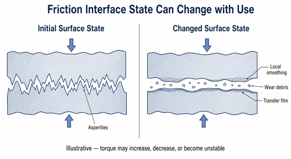
Illustrative interface changes caused by running-in, local smoothing, material transfer, and wear debris. The resulting torque may increase, decrease, or become unstable.
No universal cycle count separates running-in from wear-out. Contact pressure, material pairing, surface process, lubricant, motion arc, speed, and contamination all change the pattern. A supplier should therefore show the actual torque trend for the proposed construction rather than apply a generic “break-in allowance.”
Loss of interface pressure
A friction interface needs normal force. That force may come from a spring element, formed clip, elastic sleeve, fastened stack, or controlled interference. Stress relaxation, polymer creep, local yielding, embedment, or permanent set can reduce contact pressure even when the hinge looks unchanged from the outside.
The correct material response depends on stress level, temperature, time, geometry, processing condition, and contact design. A material name alone cannot prove preload retention. Avoid generic claims that one stainless grade, heat treatment, or spring alloy will always retain more torque. That decision belongs in a design-specific material review supported by test evidence.
Lubricant migration and condition change
In a lubricated hinge, the amount and location of grease can matter as much as its product name. Repeated motion can redistribute grease. Oil can separate from the thickener. A lubricant can be displaced from one contact zone and accumulate in another. Cleaner, disinfectant, dust, or an incompatible assembly chemical can alter the interface.
These changes do not always reduce torque. A dry or contaminated contact may become rougher and produce a torque spike, stick-slip, noise, or seizure. Another interface may become smoother and lose running resistance. This is why “lubrication failure” is too broad for a root-cause statement. Record whether breakaway, running torque, direction, noise, temperature response, or visual residue changed.
Contamination, corrosion, and chemical exposure
Particles can create abrasive wear or jam a local contact. Corrosion products can increase roughness, remove material, change clearances, or restrict motion. Chemical exposure can attack a polymer friction element, seal, coating, or lubricant. The resulting torque may move upward, downward, or become erratic; the direction alone does not identify the contaminant.
Environmental evidence should include the actual fluid or contaminant, exposure method, temperature, duration, cleaning sequence, and whether the hinge was moving during exposure. Salt-spray hours or a material label cannot substitute for functional torque measurements before and after the defined exposure. Detailed corrosion-grade selection remains with the torque hinge material guide.
Thermal dimensional change and permanent set
Different components expand and contract at different rates. Within the intended range, the resulting torque shift may be reversible. Outside the validated range, an interference feature, polymer element, housing, or spring component may take a permanent set. Proof requires a return-to-reference measurement. A low result at temperature by itself cannot separate viscosity change from dimensional change or permanent damage.
A Baseline That Survives Comparison
The baseline is part of the specification, not merely the first number in a spreadsheet. If the initial reading is taken on an unconditioned hinge, at an uncontrolled temperature, or with a hand-operated fixture, a later difference may reflect the method rather than product change.
Define when the baseline is taken. A program may need an as-received value, a value after a stated conditioning sequence, or both. Neither is universally correct. The useful reference is the one tied to the product requirement and repeated at later checkpoints.
| Controlled item | Why it changes the result | What the test method must state |
|---|---|---|
| Specimen identity | Model revision, lot, process route, and paired components may differ | Part number, revision, lot or batch, sample ID, and build state |
| Conditioning history | Early interface redistribution can change torque | As-received or conditioned status, motion arc, count, speed, dwell, and direction |
| Temperature | Lubricant rheology, clearances, and material dimensions are temperature-dependent | Ambient and specimen temperature, stabilization method, soak time, and measurement delay |
| Angle and direction | Torque can vary through the travel and by opening or closing direction | Start angle, end angle, measurement window, orientation, and direction |
| Rotation rate and dwell | Friction, self-heating, and breakaway can depend on speed and rest time | Angular speed or motion profile, dwell before start, and dwell at reversals |
| Fixture and parasitic load | Misalignment, radial load, cable drag, or fixture friction can add to the reading | Fixture drawing, sensor range, coupling, alignment method, tare or fixture check, and data rate |
| Reported torque metric | Peak, average, minimum, and value at one angle answer different questions | Exact calculation window and separate opening and closing results |
The torque sensor should operate in a suitable range for the expected signal, with calibration or verification appropriate to the company’s quality system. Sensor capacity alone is not enough. A large-capacity sensor may resolve a small hinge signal poorly, while a fixture with side loading can create a repeatable but irrelevant number.
Component versus assembly: A coaxial component fixture helps isolate internal hinge change. A loaded-panel test confirms whether the product still performs its system function. Use both when the project risk justifies it, but do not treat the two results as interchangeable.
Lifecycle Testing Without a False Failure
A cycle count without a motion profile is not reproducible. The same number of cycles can produce different wear and temperature histories when the angle, speed, dwell, reversal, stop impact, external load, and duty cycle differ. The test profile needs to represent the damaging features of service without introducing a new mechanism that the product will not encounter.
Separate cycling from measurement
High-speed cycling may be practical for durability, but torque checkpoints should return to a defined measurement condition. Stop the cycle profile, allow the specified recovery or stabilization period, and measure at the reference speed, direction, angle window, and temperature. Otherwise, the checkpoint combines permanent change with whatever heat and shear state exists at that moment.
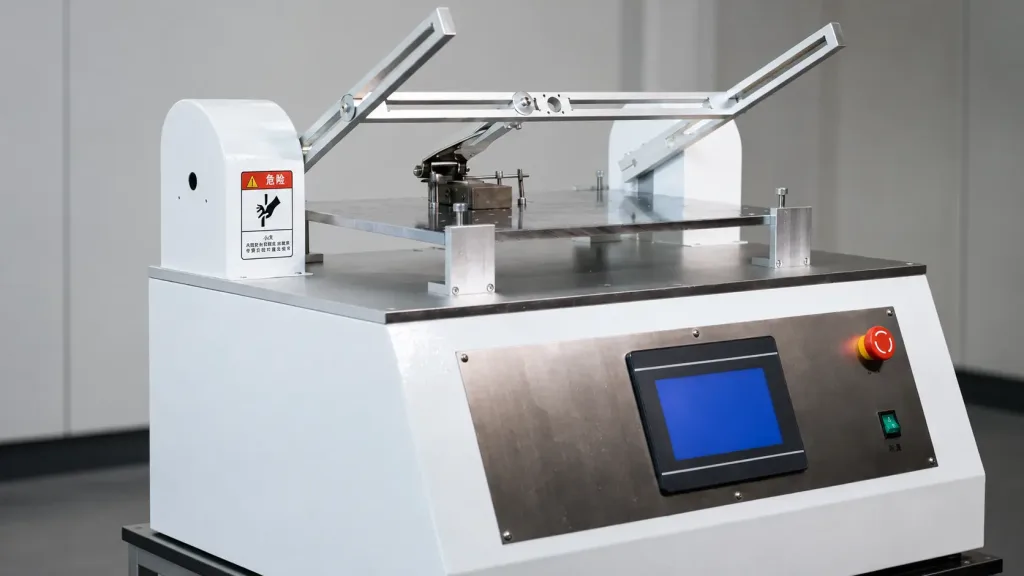
Lifecycle cycling equipment applies repeated motion to hinge specimens. Reference torque checkpoints still require a controlled measurement method after recovery or stabilization.
Record temperature close enough to the hinge to identify self-heating. Ambient temperature alone may not reveal the friction-interface condition. If the hinge becomes materially warmer as cycle speed increases, the accelerated profile needs engineering review rather than an assumption that faster testing is equivalent.
Use checkpoints that show the path
An initial and final reading can show that a change occurred; they cannot show when it occurred. Intermediate checkpoints distinguish an early transition, a stable region, a gradual decline, and an event-driven step. Checkpoint spacing should reflect the intended life and expected risk. It is project-specific, not a universal sequence.
Retain individual sample traces. Averages can hide one unit that falls below the functional limit while other units remain high. Report the defined statistic required by the drawing or test plan, but keep sample-level results available for root-cause review.
Environmental exposure needs a recovery check
For temperature, humidity, cleaning-fluid, or contamination studies, record torque before exposure, at the exposure condition when safe and relevant, and again after return to the reference condition. The last measurement separates an operating-state shift from lasting damage. If cycling occurs during exposure, the report must preserve that sequence.
ASTM D6184-22 can characterize the tendency of lubricating grease to separate oil under its specified elevated-temperature method. It does not define torque-hinge cycle life, dynamic grease behavior inside the hinge, or an acceptable torque change. Use it only as supporting lubricant-screening evidence, not as a substitute for functional hinge testing.
Torque Retention and the Functional Window
Torque retention expresses a checkpoint result relative to the defined baseline:
Rn = (|Tn| ÷ |T0|) × 100%
|T0| is the magnitude of the baseline torque and |Tn| is the magnitude at checkpoint n, measured using the same defined method and sign convention. Calculate opening and closing retention separately where direction matters. If the metric uses an average over an angle window, preserve that same window and calculation at every checkpoint.
A percentage limit alone is not enough. A high initial sample can retain an acceptable percentage yet finish above the force an operator can comfortably move. A low initial sample can retain the same percentage and finish below the moment required to hold the panel. The absolute functional window is therefore the primary end-of-life criterion. Add a relative retention requirement when the project also needs to control change from the baseline.
- An absolute functional window that protects holding performance, user force, direction, and any local low point through the working angle.
- A retention requirement, when needed, that limits change relative to the project-defined baseline.
These values are project-specific. Do not copy another product’s cycle count, initial tolerance, or retention percentage into a drawing. Treat every supplier cycle claim as model- and method-specific unless the supporting report defines broader applicability. The OEM still needs an acceptance condition matched to its own load, motion, and safety consequence.
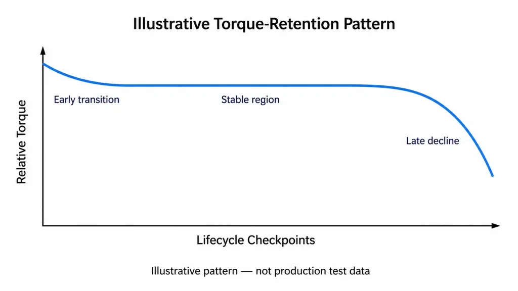
Illustrative torque-retention pattern showing an early transition, stable region, and late decline. This is not production test data.
Read the Curve Before Naming the Cause
A torque-versus-cycle plot shows when output changed. A torque-versus-angle plot shows where and in which direction it changed. Neither curve identifies wear, preload relaxation, or lubricant migration by itself, but each can eliminate weak explanations and direct the next inspection.
| Measured pattern | What the data can support | Next evidence |
|---|---|---|
| An early change followed by a repeatable plateau | A transition toward a stable interface state is possible | Confirm that the plateau remains inside the functional window and inspect whether the specification uses a conditioned baseline |
| A gradual decline across several checkpoints | A cumulative mechanism is active | Compare sample traces, surface condition, preload features, lubricant location, temperature history, and debris |
| A sudden step after one cycle block or event | A discrete event is more likely than smooth progressive wear | Review stop impact, fixture movement, fastener or coupling slip, overload, contamination event, and data logs |
| Torque changes at temperature and returns after reconditioning | The change is primarily reversible under the tested sequence | Confirm repeatability and judge whether the in-temperature result still meets the application requirement |
| One direction or one angular region changes first | The behavior is localized or asymmetric | Inspect contact distribution, one-way elements, stops, direction-specific loading, and the local curve rather than only the overall average |
| Large sample-to-sample spread with no shared trend | Process variation or an uncontrolled test variable may dominate | Review lot traceability, critical dimensions, assembly inputs, conditioning, fixture setup, and sensor checks |
Nominal torque passes; retention still fails
Consider two production-intent hinges that both meet the initial drawing value. One was measured after a controlled conditioning sequence; the other was measured as assembled. After the same lifecycle profile, their final running torque looks similar, but only the conditioned unit appears to retain a high percentage because the baselines were defined differently. The disagreement is not proof that one design is more durable. It is a baseline-definition error.
A second conflict can occur inside the same curve: the average remains acceptable while a short angular region falls below the moment needed to hold the real panel. The report passes. The product drifts. This is why the acceptance window, direction, and functional low point must be stated before the test begins.
This is an illustrative engineering scenario, not a customer project record or product test claim.
Controls That Match the Evidence
“Use a stronger hinge” is not a corrective action unless the evidence shows that initial capacity was the problem. Increasing preload can raise user force, contact pressure, heat, and wear. Adding lubricant can lower friction or contaminate an interface that was not designed for field lubrication. Each control needs to answer the measured mechanism.
| Evidence branch | Potential engineering control | Required verification |
|---|---|---|
| Controlled early running-in, then stable output | Define production conditioning and set the baseline after that state if the application permits | Confirm that initial user force, conditioned output, and long-term window all meet the product requirement |
| Progressive surface wear or debris generation | Review contact geometry, pressure distribution, friction-pair compatibility, surface process, lubricant strategy, and contamination exclusion | Repeat lifecycle testing on production-intent samples and inspect the contact zone at planned checkpoints |
| Loss of interface pressure | Review preload source, operating stress, elastic range, time-temperature exposure, creep-sensitive parts, and stack retention | Measure torque retention after combined dwell, temperature, and cycle conditions relevant to service |
| Temperature- or rate-dependent torque outside the functional window | Review lubricant, clearances, friction materials, motion rate, thermal path, and required operating range | Test at stabilized low, reference, and high conditions, then repeat after recovery |
| Lubricant migration, separation, or incompatibility | Control lubricant type, amount, application location, compatible chemicals, storage, and assembly cleanliness | Use lubricant screening as supporting evidence and confirm function in the complete hinge over the defined profile |
| Corrosion or contamination changes the interface | Review sealing, drainage, coating, material pairing, cleaner exposure, and ingress path | Combine the project exposure with pre- and post-exposure torque curves; do not judge only by appearance |
| Wide lot or sample variation | Identify torque-critical dimensions and assembly inputs, improve traceability, and review process capability | Compare multiple production-intent lots using the same fixture, conditioning, and calculation method |
Material and surface choices should follow the actual mechanism. Hardened contact parts, stainless components, engineered polymers, coatings, and dry or lubricated interfaces all have valid uses. None is a universal remedy. The selected configuration still needs evidence over the project’s load, temperature, environment, motion, and life profile.
Put Retention on the Test Plan
A purchase drawing that lists only nominal torque leaves the most important lifecycle questions unresolved. The supplier does not know which direction, angle, condition, or checkpoint protects the product. The OEM cannot later decide whether a changed result is acceptable without moving the acceptance boundary.
The drawing, specification, or approved test plan should define the following torque-decay fields:
- Hinge part number, revision, configuration, and torque direction.
- Reference mounting orientation and component fixture.
- As-received and/or conditioned baseline definition.
- Conditioning motion arc, speed, dwell, count, and temperature.
- Breakaway, running, and static-hold metrics that apply.
- Opening and closing calculation windows.
- Reference temperature, stabilization time, and measurement delay.
- Lifecycle angle, rate, dwell, reversals, duty cycle, and stop condition.
- Environmental sequence and whether cycling occurs during exposure.
- Intermediate measurement checkpoints.
- Absolute minimum and maximum functional torque limits.
- Project-defined torque-retention requirement, if used.
- Sample quantity, lot coverage, and production-intent status.
- Sensor range, data rate, calculation method, and traceability.
- Failure handling, inspection, and retest rule.
Values that depend on the application should be marked Project-Specific until the load, operating envelope, and user-force requirement are known. A supplier can propose a preliminary method, but the OEM must connect the final limits to the finished product. Production approval should use the released method and production-intent parts; an unrecorded bench demonstration is not equivalent.
Do not repair the specification with margin alone. A higher day-one torque may prevent drift temporarily, but it can also increase operating effort and interface stress. Retention and the absolute functional window must be reviewed together.
A Reproducible Decay Record
A defensible torque-decay review should let another engineer reproduce the comparison and understand its limits. A screenshot of one final number is not enough. Assemble the evidence in the order below.
- Identify the specimens. Record model, revision, lot, sample ID, production status, and any paired or direction-specific configuration.
- Attach the method. Include the fixture drawing or photo, sensor information, angle convention, speed, dwell, temperature method, and calculation window.
- Preserve the baseline. State whether it is as-received or conditioned and retain the original torque-angle data.
- Show the lifecycle history. Record cycle profile, checkpoints, environmental sequence, interruptions, temperature, overloads, stop events, and fixture changes.
- Report individual results. Provide opening and closing curves, retention, absolute functional limits, and sample-level exceptions rather than only an overall average.
- Separate observation from conclusion. Describe wear, residue, noise, debris, preload change, or corrosion as observed evidence. Name a root cause only when the data supports it.
- Define the next test. State whether the next action is a repeated reference test, teardown, lubricant review, material review, process study, or complete-assembly confirmation.
If the current and baseline conditions cannot be reconstructed, label the conclusion inconclusive. Collecting a new controlled baseline from retained or comparable production-intent samples is more useful than assigning a wear mechanism from field feel alone.
The product family, construction, and available evidence differ across applications. Review the current torque hinges category for the relevant configuration before comparing unrelated models or test claims.
Torque Hinge Decay FAQ: Causes, Temperature, Lubrication, and Test Evidence
What causes a torque hinge to lose strength over time?
Permanent torque loss can result from friction-interface wear, loss of preload or contact pressure, lubricant redistribution or contamination, corrosion or chemical attack, or permanent set after thermal or mechanical exposure. The dominant mechanism depends on the hinge construction and must be separated using controlled torque data together with inspection.
Can temperature temporarily make a torque hinge feel weaker?
Yes. Temperature can change lubricant rheology, clearances, material dimensions, and contact pressure. Measure after stabilization at the operating temperature and again after reconditioning at the defined reference condition. Recovery supports a reversible temperature-dependent shift rather than permanent decay.
Can adding grease restore torque that a hinge has lost?
Not reliably. Added grease may raise, lower, or destabilize friction, and an incompatible lubricant can damage the intended interface. Lubricate only when the hinge manufacturer has defined the lubricant, amount, location, and service method, then verify breakaway torque, running torque, and retention under the same controlled conditions.
Is lower torque immediately after lifecycle cycling permanent?
Not necessarily. An immediate post-cycle reading can be affected by self-heating, test rate, dwell, and the temporary shear state of the lubricant. Allow the specified recovery or stabilization period and repeat the reference measurement. Only a lower result that remains under comparable conditions supports permanent decay.
What test evidence confirms permanent torque hinge decay?
Use baseline and checkpoint measurements made with the same torque definition, specimen condition, fixture, angle window, direction, speed, dwell, and reference temperature. The lower output should remain after the specified recovery or reconditioning step and be checked against individual sample traces, not only an overall average. Preserve the torque-angle curves and full lifecycle history.
Share the Baseline and Test Conditions
If you need a project-specific torque-decay review, provide the hinge drawing or model, baseline definition, torque-angle data, opening and closing directions, fixture information, temperature and speed, lifecycle profile, checkpoint results, and photos of any residue, wear, corrosion, or damage. HTAN can use that package to identify what the present evidence supports and what still requires testing. A field symptom without comparable data will be treated as an open diagnostic condition, not a confirmed component failure.
Share Torque Data and Test ConditionsTorque hinge decay is not defined by age, cycle count, or a panel that moves. It is a persistent reduction in a stated torque or holding metric under comparable conditions. Preserve the baseline, separate reversible state changes from permanent loss, read the curve before naming the mechanism, and write both retention and the absolute functional window into the test plan.



 English
  한국어
한국어  Русский
  Español
  Italiano
  Deutsch
  Français
  Português