

How to Select Safety Guard Hinges by Machine Type
A machine guard can be easy to remove and still be wrong for the machine. The lifted door may strike an overhead cable tray. Its interlock actuator may no longer return to the same position. A technician may gain better access but have nowhere safe to place the removed panel.
That is why safety guard hinges by machine type should not be selected from a table of door weights and materials alone. Start with what the guard must do. Then account for the door load, hinge line, access frequency, maintenance envelope, interlock, contaminants, and the consequences of wear or incorrect reinstallation.
Page boundary: This guide selects the hinge architecture and the evidence needed for the guard assembly. The complete machine manufacturer remains responsible for the safeguarding strategy, risk assessment, interlock logic, stop function, and final validation.
Guard Function Before Hinge Type
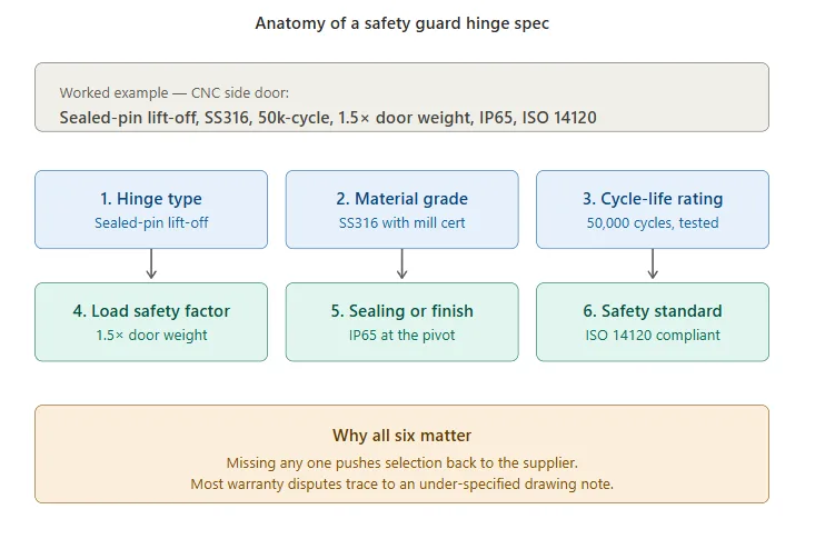
The host machine defines the environment. The guard function defines the first hinge decision. Two doors on the same CNC machine may need different structures because one is opened every shift and the other is removed only for spindle service.
| Guard Function | Normal Access | Hinge Direction to Evaluate | Questions That Must Be Resolved |
|---|---|---|---|
| Fixed guard | Removed only for defined service or machine modification | No hinge, or a captive arrangement only when the machine design treats it as a movable assembly | Why is a hinge needed? How is removal controlled? How are fixings retained? |
| Movable guard | Opened during normal production, setup, inspection, or clearing | Fixed heavy-duty, weld-on, concealed, protected-pivot, or stop-controlled structure | Opening frequency, latch, access angle, sag, contaminants, and closing repeatability |
| Interlocked movable guard | Opened only under the machine’s safeguarding logic | Low-play fixed structure or controlled-removal architecture | Interlock actuator position, wear allowance, anti-removal, defeat risk, and validation after adjustment |
| Removable maintenance guard | Comes off to clear a service path or remove a large component | Retained lift-off or another controlled removable arrangement | Lift clearance, door mass, center of gravity, handling, storage, and reinstallation alignment |
| Position-controlled cover | Opened to a required service or inspection angle | Stop, torque, assisted, or separately supported structure | Hold position, closing behavior, service support, stop load, and user force |
ISO 14120:2015 covers general requirements for the design, construction, and selection of fixed and movable guards. ISO 14119:2024 covers principles for interlocking devices associated with guards and measures intended to reduce reasonably foreseeable defeat. Neither standard selects a hinge model, material, cycle count, or load multiplier. Those remain assembly and project decisions.
For the full map of machine doors, inspection covers, operator panels, and service compartments, use the industrial machinery hinge solution. This page stays with machine safety guards.
Door Load and the Hinge Line
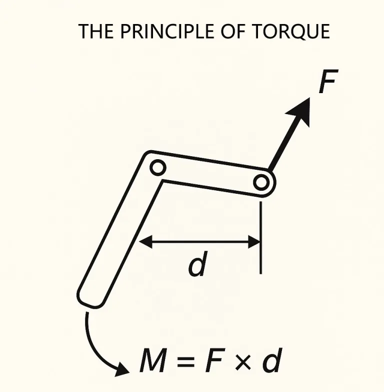
Door weight is a starting input, not the complete load case. A wide, light polycarbonate guard can create more hinge-line moment than a compact steel door. The basic static relationship is:
M = W × d
W is the complete moving weight. d is the perpendicular distance from the hinge axis to the center-of-gravity line in the evaluated position. Handles, windows, brackets, interlock actuators, cable carriers, and reinforcement move the center of gravity. Use the released assembly, not the bare panel.
The static moment does not capture every guard load. A technician may pull on the outer edge. A press frame may transmit shock. A robot-cell door may be long enough for frame twist to shift the latch side. The opening stop may generate a local peak load. None of these can be represented by a universal “two times door weight” rule.
What the Hinge Rating Must Explain
- The load direction used in the supplier rating.
- The test door or fixture geometry behind the rating.
- The hinge quantity and spacing used in the test or recommendation.
- The mounting plate, fastener, weld, or frame condition that completed the load path.
- Whether impact, vibration, opening-stop force, or misuse was included.
- The allowable play, sag, deformation, or retained alignment after the test.
For long or heavy doors, use the separate heavy-duty hinge selection guide for deeper load-path and mounting review. This article applies those inputs to safety guards rather than repeating the complete sizing topic.
When the Guard Must Come Off
A hinged door does not automatically provide useful maintenance access. When the open door blocks a motor, pump, fixture, filter, conveyor module, or tooling path, full removal may be the correct architecture. The decision depends on the complete maintenance envelope.
- Map the service path. Show the component removal direction, technician position, tools, temporary supports, and the space needed to extract the component.
- Compare swing and lift envelopes. A removable guard avoids a swing obstruction but needs vertical or angled separation clearance.
- Account for the complete panel. Weight, center of gravity, handles, windows, ground straps, sensors, and attached cables affect handling.
- Define the removal condition. State the angle, latch position, interlock condition, and retention feature that must be released before the door separates.
- Plan where the panel goes. The removed guard needs a stable storage rack, floor stand, trolley, or lifting aid that does not create a new obstruction.
- Control reinstallation. Handing, pin direction, interlock actuator, latch position, ground path, and door gaps must return to the released condition.
The access improved. The safety function did not. A tall robot-cell door may lift clear of the pins and expose the maintenance zone, yet the interlock actuator can be bent when the door is set down. When the door is rehung, it closes but no longer reaches the actuator in the same position. The removable architecture solved the space problem and created a repeatability problem.
This is an illustrative engineering scenario, not a customer project record or product test claim.
A removable hinge can reduce fastener-removal and panel-handling steps. It cannot prove a reduction in the complete mean time to repair because isolation, diagnosis, repair, reassembly, interlock verification, and restart remain part of the maintenance procedure.
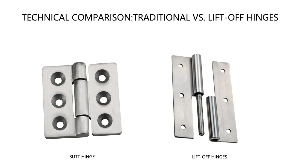
When removal is justified, review the available lift-off hinge structures by load direction, handing, mounting pattern, pin arrangement, retention, material system, and removal clearance. The product page owns models and commercial specifications; this page owns the guard-system decision.
CNC Guards: Coolant, Chips, and Service Clearance
CNC guards combine repeated access with coolant mist, chips, cleaning, and tight service space. The hinge decision changes by door position. A front operator door may need stable closing alignment over many openings. A side service door may open less often but must clear a pump, spindle unit, chip conveyor, or fixture-change path.
Pivot Exposure
Map where coolant and chips can enter the pin, bushing, leaf gap, fasteners, and frame joint. “Stainless steel” does not describe the complete interface. A corrosion-resistant leaf can still use an unsuitable pin, bushing, lubricant, or fastener. A protected or accessible pivot should be evaluated against the actual coolant and cleaning method, followed by a functional retest.
Fixture and Component Removal
A removable side guard makes sense when the swung door occupies the same volume needed to extract tooling or service equipment. Confirm the lift direction, overhead clearance, door-handling method, ground strap, sensor wiring, and where the panel will be supported. If routine access only needs a wide opening angle, a fixed hinge with a separate structural stop may be simpler and more repeatable.
- Record coolant type and cleaning exposure.
- Inspect chip paths around the hinge and latch.
- Measure the complete maintenance extraction envelope.
- Check closing alignment at the interlock and latch.
- Repeat the opening and closing test after representative contamination exposure.
Press Guards: Shock, Sag, and Retention
Press and forming equipment can transmit frame movement, impact, and repeated vibration into the guard structure. The dominant hinge risk is often not pin strength. It is movement in the complete load path: leaf, weld or bolts, backing plate, frame, latch, and interlock bracket.
Long rear or side doors should be checked for latch-side sag and frame twist under the relevant operating condition. The acceptance limit should come from the gap, latch, interlock, and guarding requirement. A universal sag limit is not useful when one machine has a large actuator capture range and another requires close positional repeatability.
Fixed and Removable Sections
A heavy-duty fixed or weld-on structure may suit the main perimeter door. A controlled removable section can still be appropriate for maintenance, but retention must prevent unintended lift during normal operation. The door mass, center of gravity, grip points, lifting height, and available handling aid decide whether manual removal is reasonable.
- Inspect frame stiffness and reinforcement at the hinge line.
- Define vibration, shock, and opening-stop inputs rather than applying a universal load factor.
- Specify the fastener or weld condition used in the supplier recommendation.
- Measure latch and interlock alignment before and after representative machine operation.
- Confirm that removable sections cannot separate in the guarded operating condition.
Robot Cells: Interlock Alignment and Anti-Removal
Robot-cell perimeter doors are often light relative to their height or width. Their functional risk comes from closing repeatability, cumulative play, fence-post movement, and the relationship between the hinge line and the interlock actuator.
ISO 14119:2024 addresses the design and selection of interlocking devices associated with guards, including guard parts that actuate the device and measures intended to reduce reasonably foreseeable defeat. The hinge does not complete that requirement by itself. Its contribution is maintaining the guard position and the intended actuator relationship over the validated condition.
Removal Changes the Interlock Boundary
When a door must come off for cell reconfiguration, the design should not allow casual removal to bypass the intended safeguarding function. Review anti-lift retention, removal angle, trapped cables, actuator protection, keying or handing, and the verification required after the cell is rebuilt.
A Long Door Is a Structure
A low-play hinge cannot compensate for a flexible fence post, thin door frame, loose latch bracket, or inadequate mounting plate. Measure the complete door edge at the actuator and latch. Record the condition after repeated movement and representative cell vibration, not only immediately after installation.
Packaging Guards: Washdown and Cleanable Joints
Packaging and filling equipment may expose a guard hinge to water, alkaline or acidic cleaners, foam, product residue, temperature change, and repeated wiping. The question is not whether the leaf carries a stainless-steel label. It is whether the full joint remains cleanable and functional.
- Drainage: identify horizontal pockets, blind gaps, pin ends, fastener recesses, and bracket interfaces that retain liquid.
- Material stack: record the leaf, pin, bushing, spring or friction parts, fasteners, washers, finish, and lubricant.
- Cleaner access: determine whether the pivot is only wiped or directly exposed to spray, foam, rinse water, or immersion.
- Removal benefit: confirm that taking off the guard exposes a real cleaning area rather than transferring contamination to an uncontrolled storage location.
- Reassembly: verify handing, latch alignment, interlock position, ground connection, and closing function after cleaning.
- Functional retest: repeat movement, play, retention, and closing checks after representative exposure.
The food processing hinge washdown guide owns the deeper material, drainage, cleaner, and corrosion discussion. A safety-guard article should not claim hygienic certification, microbial control, or a universal material grade from the hinge alone.
Woodworking Guards: Dust, Stops, and Latching
Wood dust changes the hinge problem. Fine material can pack around the pivot, prevent the latch from seating, obscure inspection, and increase friction without producing a conventional structural failure.
Place the hinge and latch where dust can be removed without forcing debris deeper into the joint. If the guard needs a defined open position, decide whether the hinge, a separate stop, or another support will carry the stop load. The required angle comes from the access and interference study, not from a standard catalog angle.
A light guard may still need reinforcement when the handle or stop loads a thin polycarbonate or mesh frame. Test the complete guard for opening, stop contact, dust contamination, closing, and latch repeatability. A clean loose hinge does not represent the contaminated assembly.
Removal Without Creating a New Hazard
Tool-free movement is not automatically safe movement. A removable guard needs a controlled handling and reinstallation condition.
| Removal Issue | Failure Introduced | Evidence or Design Action |
|---|---|---|
| Insufficient lift clearance | Door jams on an overhead frame, cable tray, duct, light, or adjacent guard | Dimension the complete lift and tilt envelope with the installed handle and interlock parts |
| Uncontrolled panel mass or center of gravity | Panel rotates during lifting or cannot be handled at the required height | Define grip points, handling aid, personnel requirement, storage support, and removal path |
| Wrong pin direction or handing | Door cannot be removed, can lift unintentionally, or is installed upside down | Control handing, pin orientation, retention, and removal angle on the drawing and BOM |
| Unprotected interlock actuator | Actuator bends or loses its released relationship during storage or reinstallation | Protect the actuator, define the storage orientation, and verify alignment after reassembly |
| Attached cable or ground strap | Cable is pulled, ground path is lost, or the panel cannot be fully removed | Define disconnects, captive connectors, strap length, and reconnection verification |
| No controlled storage location | Guard blocks an aisle, damages the hinge half, or creates a trip and impact hazard | Provide a rack, trolley, stand, or restrained location near the service task |
| Incorrect reinstallation | Latch gap, guard overlap, or interlock position changes without being noticed | Use keyed features where appropriate and repeat the guard-function check before release |
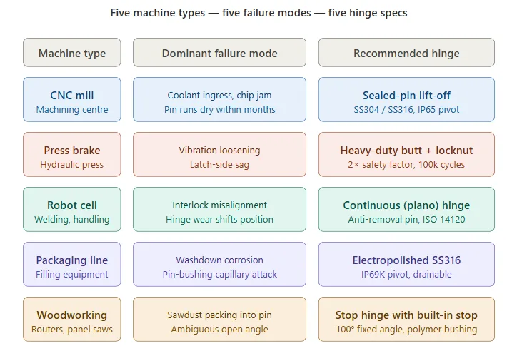
Machine-Type Selection Reference
This table narrows the architecture to evaluate. It does not replace the guard classification, load-path review, or machine validation.
| Machine Type | Guard and Access Task | Dominant Risk | Hinge Architecture to Evaluate | Evidence Needed |
|---|---|---|---|---|
| CNC machining center | Repeated operator access or full side access for tooling and component service | Coolant ingress, chip packing, blocked maintenance envelope, closing misalignment | Protected-pivot fixed hinge, heavy-duty structure, retained lift-off where complete removal is justified, or position-control structure for a top cover | Door load and CG, coolant exposure, service envelope, removal clearance, latch/interlock repeatability |
| Press or forming machine | Heavy access door exposed to frame movement, shock, or vibration | Sag, mounting movement, latch shift, unintended lift of a removable section | Heavy-duty bolt-on or weld-on structure; retained removable architecture only for a controlled maintenance task | Load path, frame input, reinforcement, fastener/weld condition, retention, latch and interlock alignment |
| Robot cell | Interlocked perimeter access and occasional reconfiguration | Actuator misalignment, long-panel flex, play, unauthorized or uncontrolled removal | Low-play fixed hinge or controlled-removal structure with anti-lift and reinstallation checks | Door-edge movement, post-cycle alignment, actuator clearance, fence stiffness, removal control |
| Packaging or filling line | Frequent access under washdown or chemical cleaning | Cleaner ingress, retained liquid, corrosion, incorrect reassembly after cleaning | Drainable or protected pivot; controlled removable hinge where full cleaning access is demonstrated | Cleaner and exposure method, drainage, material stack, post-cleaning function, interlock and latch check |
| Woodworking machine | Light or medium guard requiring dust access, reliable closing, and a defined open condition | Dust packing, incomplete latching, stop overload, thin-panel deformation | Accessible pivot with appropriate stop/support and reinforced mounting where needed | Dust path, cleaning access, stop load, panel stiffness, closing and latch repeatability |
Drawing and Sample Data for Approval
A drawing note such as “stainless safety hinge, heavy duty, ISO compliant” does not define the guard behavior. Put the assembly inputs and acceptance evidence where the supplier and OEM can review the same condition.
- Guard classification: fixed, movable, interlocked movable, removable maintenance guard, or position-controlled cover.
- Machine and access task: machine type, guard location, normal access frequency, maintenance task, and component-removal path.
- Moving assembly: width, height, thickness, complete weight, center of gravity, handles, windows, brackets, attached devices, and cables.
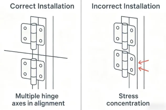
- Hinge arrangement: quantity, spacing, axis position, opening direction, handing, pin direction, mounting face, and available envelope.
- Mounting structure: frame and panel material, thickness, reinforcement, weld or fastener condition, rear access, and allowable distortion.
- Guard interfaces: latch, overlap, opening stop, interlock actuator, ground strap, gasket, cable route, and adjacent panels.
- Removal requirements: lift or tilt clearance, removal angle, anti-lift retention, handling method, storage position, and reinstallation control.
- Operating exposure: coolant, chips, dust, moisture, cleaning agent, temperature, vibration, shock, and maintenance condition.
- Use profile: opening range, representative movement count, speed, dwell, impact or misuse inputs, and inspection interval where relevant.
- Acceptance evidence: fit, door gaps, free play, latch and interlock alignment, opening behavior, stop function, removal/reinstallation, post-exposure movement, and retained condition after the agreed test.
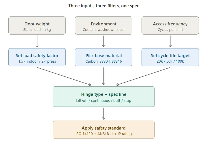
A preliminary hinge recommendation should be checked on the actual guard, frame, latch, interlock, and operating environment before production approval. Generic OEM approval stages do not need another section here; the specific sample evidence above is what closes this task.
Send HTAN the machine-guard drawing, door weight and center of gravity, hinge line, maintenance path, interlock position, contaminants, and removal requirement. The review can then focus on a suitable structure and the evidence that still needs to be confirmed on the assembly.
FAQs
When should a machine safety guard use lift-off hinges?
Evaluate lift-off hinges when the complete guard must be removed to clear a maintenance, tooling, cleaning, or component-extraction path. Confirm the lift or tilt clearance, panel weight and center of gravity, handling and storage method, anti-lift retention, attached cables or ground straps, interlock protection, and reinstallation checks before approving the removable layout.
Can an interlocked machine guard door be removable?
It can be designed as a controlled removable guard when the machine-level safeguarding strategy permits it. The design must preserve the intended interlock relationship, prevent uncontrolled or reasonably foreseeable defeat, protect the actuator during handling, and require the completed guard function to be checked after reinstallation. The hinge alone does not establish compliance.
Do lift-off hinges automatically reduce machine MTTR?
No. They can reduce fastener-removal and panel-handling steps when full guard removal improves access. Complete MTTR also includes isolation, diagnosis, repair, reassembly, interlock verification, and restart. Measure the actual maintenance procedure before claiming a time or financial improvement.
How should a heavy removable guard be handled safely?
Define the complete panel weight, center of gravity, grip points, lifting height, removal direction, personnel or lifting-aid requirement, and a stable storage location. Split hinge construction can simplify alignment, but it does not prove that one-person handling is safe. Validate the real handling task on the machine.
What data should be included in a safety guard hinge drawing?
Include the guard classification, machine and access task, panel dimensions, complete weight and center of gravity, hinge quantity and spacing, axis and handing, mounting structure, latch and interlock interfaces, contaminants, opening or removal envelope, retention, handling method, use profile, and the assembly-level acceptance checks.


 English
  한국어
한국어  Русский
  Español
  Italiano
  Deutsch
  Français
  Português