Dobradiças de binário ajustável: Princípios, estrutura e aplicações
Na conceção de engenharia, como é que se consegue que uma tampa ou um expositor pesado se mantenha em qualquer ângulo (Controlo de Posição), sem "cair lentamente" com o tempo?
As soluções tradicionais de molas a gás são complexas e propensas a falhas. A verdadeira solução é a Dobradiça de Torque Ajustável - um componente que fornece resistência de retenção constante usando apenas "fricção controlada" interna para um posicionamento preciso.
Mas como é que os engenheiros evitam a falha de conceção mais comum: o erro de cálculo do binário?
Este guia definitivo fornece a resposta definitiva, desde as normas fundamentais de física e fiabilidade (como os testes de 25 000 ciclos) até aos cálculos precisos.
O que é uma dobradiça de binário ajustável?
Definição exacta da dobradiça de binário ajustável
Definição do núcleo:
Uma dobradiça de torque ajustável é um tipo especial de dobradiça mecânica. A sua função principal é fornecer uma resistência constante e previsível ao longo de toda a gama de movimentos rotativos da dobradiça através de um mecanismo interno integrado de "fricção controlada".
Esta resistência é designada por binário.
Caraterísticas principais:
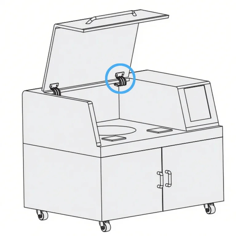
Esta resistência constante permite que a dobradiça atinja uma função de "controlo de posição".
Com esta função, os utilizadores podem mover suavemente portas, coberturas, ecrãs ou braços para qualquer ângulo desejado e, depois de soltar, o objeto mantém-se automaticamente nessa posição - sem necessidade de quaisquer dispositivos de bloqueio adicionais, molas a gás ou barras de suporte.
O significado de "ajustável":
Diferente dobradiças de binário fixoA caraterística "ajustável" significa que os utilizadores - normalmente engenheiros ou técnicos no local - podem definir ou alterar com precisão o binário de fricção durante a utilização através de um mecanismo de ajuste externo na dobradiça (como um parafuso de ajuste).
Isto permite que a dobradiça se adapte a diferentes pesos de carga ou compense a degradação do desempenho após uma utilização prolongada.
O valor do "controlo da posição"
A função de "controlo de posição" é o valor comercial e de engenharia mais importante das dobradiças de binário ajustável.
Simplificar a conceção e reduzir os custos:
Elimina a necessidade de componentes de suporte auxiliares, tais como molas a gás, pinos de bloqueio mecânico, fechos magnéticos ou limitadores.
Reduzir os pontos de falha:
Esta conceção simplificada não só reduz o custo da lista de materiais (BOM) do produto, como também minimiza significativamente o potencial de pontos de falha.
Melhorar a experiência do utilizador:
Proporciona aos utilizadores finais uma experiência tátil topo de gama, suave e silenciosa.
Quando se deslocam coberturas pesadas ou se ajustam monitores médicos, esta sensação de amortecimento controlado e suave é um indicador-chave da qualidade do produto.
Distinção essencial: Dobradiça de torque vs. Dobradiça de amortecimento vs. Dobradiça de mola
Nas aplicações industriais, estes três tipos de dobradiças funcionais são frequentemente confuso. Embora dobradiças amortecedoras e as dobradiças de mola também geram binário num sentido lato, a sua mecanismos físicos e objectivos da aplicação são completamente diferentes.
Dobradiça de binário ajustável (de fricção):
A sua resistência provém de fricção estática forçao que significa que o seu binário de saída é independente da velocidade angular.
Quer o utilizador mova o painel de forma rápida ou lenta, a resistência (binário) mantém-se constante.
Esta é a base física para alcançar "controlo de posição".
Dobradiça de amortecimento:
A sua resistência tem origem na cisalhamento de fluidos viscosos (como o óleo de silicone), pelo que o seu binário de saída é fortemente relacionado com a velocidade angular.
Quanto mais rápido for o movimento, maior será a resistência.
A sua principal função é "buffering" ou "fecho suave", como nas portas de armários, e não pode parar em nenhuma posição intermédia.
Dobradiça de mola:
Este tipo armazena e liberta energia potencial (por exemplo, molas de torção).
A sua principal função é "fecho automático" ou "auto-abertura" (como se vê nas portas corta-fogo ou nas caixas de jóias).
É verdade não fornecer uma resistência constante.
Tabela de comparação do desempenho das principais dobradiças funcionais
| Caraterística | Dobradiça de torque ajustável | Dobradiça de amortecimento | Dobradiça de mola |
|---|---|---|---|
| Princípio fundamental | Fricção estática controlada (Fricção) | Cisalhamento de fluidos viscosos (Viscosidade) | Energia Potencial Elástica (Mola) |
| Caraterística de resistência | Binário constante (independente da velocidade) | Binário relacionado com a velocidade | Binário relacionado com o ângulo |
| Função principal | Controlo de posição | Fecho suave / Buffering | Fecho automático/abertura |
| Ajustabilidade | Ajustável | Normalmente não ajustável | Normalmente não ajustável |
| Aplicação típica | Monitores médicos, protecções industriais, máquinas POS | Portas de armários topo de gama, assentos de sanita | Portas corta-fogo, tampas de caixa com fecho automático |
Análise aprofundada do princípio de funcionamento - Física de "fricção controlada
Modelo físico principal: Fonte de binário
Todo o segredo das dobradiças de binário ajustável reside no controlo preciso da força de fricção estática.Princípio básico: O binário de rotação (τ) da dobradiça provém da força de fricção (Ff) gerada entre as placas de fricção internas.Fórmula física: Força de Atrito Ff = μ × N, onde μ é o coeficiente de atrito estático entre os materiais das placas de atrito, e N é a força normal aplicada às placas de atrito.Núcleo do Projeto: Os objectivos de conceção de toda a dobradiça são dois: manter a estabilidade do valor μ durante uma vida útil extremamente longa (por exemplo, superior a 25.000 ciclos); fornecer aos utilizadores um mecanismo fiável para ajustar N com precisão.
Mecanismo chave: Ajuste da "Força Normal"
A "ajustabilidade" da dobradiça é essencialmente o ajuste da "força normal N": A dobradiça contém internamente um ou mais conjuntos de placas de fricção sobrepostas (ou anéis de fricção): Quando o utilizador aperta o "parafuso de ajuste" externo, o parafuso empurra uma placa de pressão ou um conjunto de Anilhas de BellevilleTransmissão de força: Estas molas aplicam uma pressão axial precisa e sustentada (i.e., "força normal N") a toda a pilha de placas de fricção.Resultado: Quanto mais apertado for o parafuso de ajuste, maior será N, levando a um aumento da força de atrito Ff e, em última análise, a um aumento do binário de saída da dobradiça τ.A utilização de anilhas Belleville é o engenho deste design. Elas proporcionam uma curva de pressão relativamente constante. Mesmo que as placas de fricção sofram um pequeno desgaste que leve à redução da espessura após uma utilização prolongada (como após 25.000 ciclos), as molas podem compensar automaticamente esta alteração, mantendo assim o binário dentro do intervalo ±20% da especificação durante todo o ciclo de vida.
Curva caraterística de binário constante
Se for desenhado um gráfico da relação "binário vs. ângulo de rotação" de uma dobradiça de binário ideal, a sua curva deverá ser basicamente uma linha reta. Isto significa que, independentemente do facto de a tampa estar a 10°, 45° ou 90°, o binário de retenção fornecido pela dobradiça é constante. Isto forma um forte contraste com as curvas das dobradiças de mola (o binário varia com o ângulo) e das dobradiças de amortecimento (o binário varia com a velocidade).
Desmontagem da estrutura interna e ciência dos materiais
Responder primeiro: Quatro componentes principais
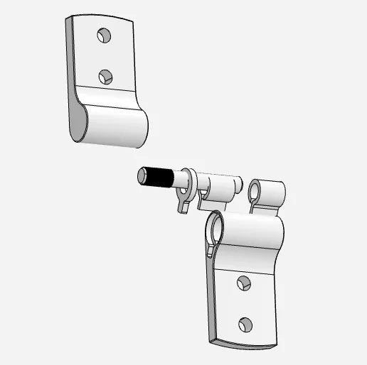
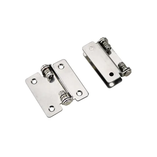
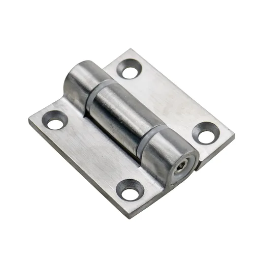
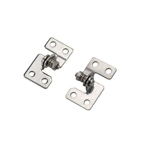
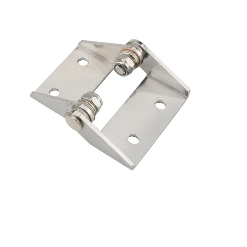
As formas e tamanhos das dobradiças de binário ajustável variam, mas as suas estruturas centrais são todas compostas pelos seguintes quatro tipos de componentes-chave:Eixo/Pino: Eixo central de suporte de carga, transmite o binário. Deve ter alta resistência ao cisalhamento e alto acabamento superficial para reduzir o desgaste em áreas sem atrito.Discos de fricção: O coração que gera o binário. Esta é a tecnologia central da dobradiça, geralmente aparecendo em pares (um fixo no eixo, um fixo na carcaça).Mecanismo de ajuste: Como descrito acima, o sistema usado para aplicar e alterar a "força normal N", geralmente consistindo de um parafuso de ajuste e arruelas Belleville (ou peças de mola similares).Carcaça: Protege os componentes internos da poluição ambiental, como poeira e humidade, e fornece interfaces de montagem padronizadas (como orifícios para parafusos) para fixação ao produto.
Ciência dos materiais: Equilíbrio entre desempenho e custo
A seleção do material da dobradiça determina a sua resistência, vida útil, durabilidade e custo, e deve ser rigorosamente escolhida com base no seu cenário de aplicação final.
Comparação do desempenho de materiais comuns de dobradiças e cenários de aplicação
| Tipo de material | Vantagens principais | Principais desvantagens | Cenários de aplicação típicos | Normas associadas/desempenho |
|---|---|---|---|---|
| Aço inoxidável (por exemplo SUS304) | Excelente resistência à corrosão, resistência a altas temperaturas, alta resistência, fácil de limpar e esterilizar | Elevado custo, elevada dificuldade de processamento | Equipamento médico (que requer esterilização), maquinaria de processamento de alimentos, equipamento para ambiente exterior ou marinho | Em conformidade com o teste de calor húmido IEC 60068-2-78; compatível com salas limpas |
| Liga de zinco (por exemplo Zamak) | Baixo custo, fácil de fundir em formas complexas, boa galvanoplastia e aderência do revestimento | Resistência e resistência à corrosão inferiores às do aço inoxidável, fraca fluência a longo prazo | Periféricos de eletrónica de consumo (máquinas POS), mobiliário de escritório, portas de armários de interior | Aplicações sensíveis ao custo, requisitos de vida útil moderados (por exemplo, <20 000 ciclos) |
| Plásticos de engenharia (tais como PEEK, PA) | Extremamente leve, auto-lubrificante (baixo ruído), resistência química, isolamento elétrico, não magnético | Menor capacidade de carga e rigidez, sensível a alterações de temperatura | Instrumentos de diagnóstico médico leves, interiores de aviação (redução de peso), coberturas de equipamento eletrónico, equipamento para salas de ressonância magnética | Tendências de miniaturização; satisfazer as necessidades de ambientes especiais (como os não magnéticos) |

Normas autorizadas e verificação de desempenho
Responder primeiro: Normas básicas para avaliação de dobradiças de torque
A "fiabilidade" de uma dobradiça de binário não depende da sua cópia promocional, mas do facto de ter sido aprovada em testes padrão reconhecidos pela indústria. Em aplicações críticas (tais como medicina, aviação, indústria pesada), as dobradiças sem certificação padrão representam enormes riscos de segurança. Os engenheiros profissionais devem solicitar aos fornecedores, durante a seleção, relatórios de teste para as seguintes normas.
Teste de ciclo de vida
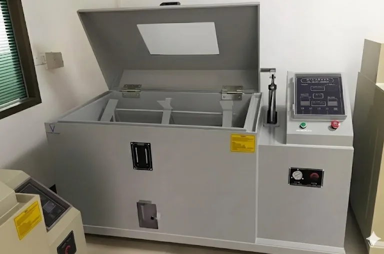
Dados essenciais: Uma referência de alta qualidade reconhecida na indústria é >25.000 ciclos de vida.Indicador de degradação de desempenho: O simples facto de completar 25.000 ciclos não é suficiente. O indicador mais crítico é que, no final do ciclo de vida, o seu binário dinâmico deve permanecer dentro de ±20% da especificação de binário estático original. Este ±20% é um fator chave que deve ser considerado no design. Isso significa que uma dobradiça com um torque nominal de 10 N・m pode ter apenas 8 N・m de força de retenção no final da vida útil. Isso se relaciona diretamente com o cálculo da "margem de segurança" na quinta parte - o projeto deve compensar isso.Números de referência da norma:ANSI/BHMA A156.17: O American National Standards Institute (ANSI) emitiu uma norma sobre ferragens para mobiliário (incluindo dobradiças de fecho automático e de oscilação livre), o seu método de ensaio de ciclo tem um valor de referência importante.DIN EN 1935: Norma alemã/UE sobre ferragens (dobradiças de eixo único), embora principalmente para portas, os seus métodos definidos de ensaio de ciclo e de ensaio de carga são industriais.
Ensaios de adaptabilidade ambiental
O desempenho das dobradiças pode mudar significativamente sob diferentes temperaturas e humidades. As normas da série IEC 60068 são o padrão de ouro internacional para avaliar a fiabilidade dos componentes electrónicos e mecânicos em diferentes ambientes.IEC 60068-2-1): Garante que a dobradiça não falha ou encrava devido à fragilidade do material (especialmente peças de plástico) ou a mudanças drásticas nas placas de fricção (valor μ) a baixas temperaturas (como -10°C).Teste de calor seco (IEC 60068-2-2): Garante que as peças de plástico de engenharia não amolecem a altas temperaturas (como +50°C ou mais) e que o binário de fricção não sofre uma "degradação térmica" irreversível: Simula ambientes extremamente húmidos (como 40°C, 90% de humidade relativa), centrando-se em testar a resistência à ferrugem das dobradiças de aço inoxidável e se os materiais de fricção falham devido à absorção e expansão da humidade.
Referência rápida para números de normas técnicas de dobradiças de chave
| Número padrão | Nome da norma (ou conteúdo principal) | Objetivo do teste |
|---|---|---|
| 3 (Dados citados) | Teste do ciclo de vida do fabricante | Verificar se a degradação do binário se mantém dentro de ±20% após >25.000 ciclos |
| IEC 60068-2-1 | Ensaios ambientais - Parte 2-1: Ensaio A: Frio | Avaliar o impacto da baixa temperatura no coeficiente de atrito (μ) e na fragilidade do material |
| IEC 60068-2-2 | Ensaios ambientais - Parte 2-2: Ensaio B: Calor seco | Avaliar o impacto da temperatura elevada na degradação e na fluência do desempenho do material de fricção |
| IEC 60068-2-78 | Ensaios ambientais - Parte 2-78: Cabina de ensaio: Calor húmido em estado estacionário | Avaliar a resistência do material à corrosão e à expansão por absorção de humidade |
| ANSI/BHMA A156.17 | Dobradiças (de fecho automático e de oscilação livre) | Referência da indústria norte-americana de mobiliário e ferragens em termos de ciclo de vida e carga |
Guia de seleção e cálculo preciso do binário
Responder primeiro: Razão principal para o insucesso da seleção
A razão mais comum para a falha na seleção da dobradiça é o erro de cálculo do binário. Isso geralmente se manifesta como: Subestimar a demanda real de torque: O que leva a que a dobradiça não seja capaz de "controlar a posição" na posição horizontal e que a cobertura descaia lentamente.CdG): Dividir cegamente o comprimento da cobertura por 2, o que leva a um desvio de cálculo.
Fórmulas autorizadas para o cálculo do binário (Three-Tier Evolution)
Várias fontes fornecem fórmulas de cálculo do bináriocom precisão variável.
Primeiro nível (fórmula de estimativa):
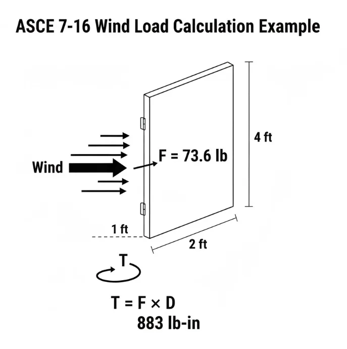
Aplicável aos casos em que o material da cobertura é uniforme e o centro de gravidade está exatamente no centro geométrico. Binário (T, unidade N\cdotpm)=Peso da cobertura (W, unidade kg)×9,8 (g)×Comprimento da cobertura (L, unidade m)2\text{Binário (T, unidade N-m)} = \text{Peso da cobertura (W, unidade kg)} \times 9.8 \, (\text{g}) \times \frac{\text{Comprimento da cobertura (L, unidade m)}}{2}Torque (T, unidade N\cdotpm)=Peso da cobertura (W, unidade kg)×9,8(g)×2Comprimento da cobertura (L, unidade m)
Isto corresponde aos algoritmos "Altura da porta × 1/2 × Peso da porta" e "C / 2 × L × 9,8".
Segundo nível (Fórmula precisa) (Recomendado):
Aplicável quando o centro de gravidade não se encontra no centro geométrico (tal como coberturas com ecrãs ou pegas instalados). Torque (T, unidade N\cdotpm)=Peso da tampa (W, unidade kg)×9,8 (g)×Distância horizontal do centro de gravidade ao pivô (X1, unidade m)\text{Torque (T, unidade N-m)} = \text{Peso da tampa (W, unidade kg)} \times 9.8 \, (\text{g}) \times \text{Distância horizontal do centro de gravidade ao pivô (X1, unidade m)}Torque (T, unidade N\cdotpm)=Peso da cobertura (W, unidade kg)×9,8(g)×Distância horizontal do centro de gravidade ao pivô (X1, unidade m)
Isto corresponde ao algoritmo "Distância horizontal X1 do centro de rotação à posição do centro de gravidade × Peso m".
Terceiro nível (fórmula dinâmica):
Aplicável a aplicações que necessitem de analisar alterações de binário ao longo de todo o processo de movimento da cobertura. T(θ)=W×g×Lcog×cos(θ)T(\theta) = W \times g \times L_\text{cog} \times \cos(\theta)T(θ)=W×g×Lcog×cos(θ)
Em que LcogL_\text{cog}Lcog é a distância em linha reta do centro de gravidade ao pivot e θ\thetaθ é o ângulo entre a cobertura e o plano horizontal.
Esta fórmula indica que quando a cobertura está na posição horizontal (θ=0∘\theta = 0^\circθ=0∘), cos(0∘)=1\cos(0^\circ) = 1cos(0∘)=1, e o binário necessário é máximo. Portanto, a seleção da dobradiça deve ser baseada neste binário máximo.
Exemplo de cálculo
Dado: Comprimento da cobertura (L) = 0,5 m; Peso da cobertura (W) = 3 kg. Assumir: A cobertura é uniforme, centro de gravidade no centro (L/2 = 0,25 m).Calcule o Torque Máximo T:T = W × g × (L / 2)T = 3 kg × 9,8 m/s² × 0,25 mT = 7,35 N-m
Considerações importantes: Por que razão deve ser adicionada uma margem de segurança 30%?
Depois de calcular 7,35 N-m acima, não escolha absolutamente uma dobradiça com um limite superior de binário de 8 N-m. A melhor prática da indústria recomenda adicionar pelo menos uma margem de segurança de 30%. Binário de seleção = 7,35 N-m × 1,3 = 9,55 N-m. Os engenheiros devem escolher uma dobradiça cuja faixa ajustável possa facilmente cobrir 9,55 N-m (por exemplo, um modelo de 5-12 N-m). Esta margem de segurança 30% é usada para compensar a: Degradação da vida útil: Cobrir a degradação de desempenho de ±20% mencionada na norma.Erro de Estimativa do Centro de Gravidade: Compensar a incerteza na medição do CoG.Carga dinâmica: Compensar a carga adicional resultante do fecho rápido da cobertura por parte do utilizador (força de impacto) ou da colocação de itens adicionais na cobertura (tais como chávenas de café).
Análise de casos de cenários de aplicações inter-domínios
As dobradiças de binário ajustável, com as suas caraterísticas de "controlo de posição" e "ajustável", resolvem os principais desafios de engenharia em vários domínios.
Aplicação industrial
Caso: Portas de armários de controlo pesados, protecções de segurança de máquinas, painéis de inspeção em linhas de produção automatizadas: Impedir que protecções pesadas ou portas de armários com dezenas de quilogramas se fechem subitamente, causando lesões por esmagamento nos braços dos operadores (em conformidade com OSHA Conveniência: Em ambientes fabris estreitos, permitir que as portas de manutenção permaneçam em qualquer ângulo de abertura (como 45°), facilitando a manutenção sem que os operadores segurem a porta com as mãos ou o corpo.
Equipamento médico
Caso: Braços de monitores de cabeceira, ecrãs de equipamento de diagnóstico (como ultra-sons), braços de posicionamento de lâmpadas sem sombras em salas de operações, cadeiras de tratamento dentário: Proporciona uma experiência de ajuste sem ruído e sem vibrações, evitando perturbar os pacientes em repouso: O pessoal médico pode ajustar facilmente a posição do ecrã com uma mão e torná-lo "controlo de posição", enquanto a outra mão pode continuar a operar o equipamento ou a cuidar dos doentes.Limpeza: O design em aço inoxidável selado (consulte a Secção 3.2) é fácil de desinfetar e esterilizarA sua utilização é compatível com os requisitos do ambiente médico.
Comercial e eletrónica
Casos: Ecrãs de terminais POS (caixas registadoras), suportes de computadores portáteis topo de gama, caixas de instrumentos portáteis, ecrãs montados na cabeça AR/VR: Proporcionar uma "sensação de amortecimento" sólida, suave e de alta qualidade. Este feedback tátil é a fonte direta para os utilizadores perceberem se o produto é "topo de gama": Satisfaz as exigências de milhares de movimentos diários para ecrãs de máquinas POS (consulte a norma de vida útil de 25.000 ciclos).
Transporte
Estojo: Mesas de tabuleiro de aviões de primeira classe ou de classe executiva, ecrãs do sistema de entretenimento a bordo (IFE), veículos especiais (tais como veículos de recreio, ambulâncias), caixas de arrumação da consola central, coberturas de iates: Esta é a principal vantagem dos veículos de transporte. Em ambientes de vibração contínua de aviões, comboios ou veículos, a força de fricção estática constante garante que as mesas de tabuleiros ou os ecrãs não se movem ou cedem por si próprios, assegurando a experiência e a segurança dos passageiros.
Guia prático de instalação, ajuste e manutenção
Chave de instalação: Porque é que o "alinhamento dos eixos" é o passo principal?
90% das falhas precoces das dobradiças de binário (diminuição rápida do binário, encravamento, ruído anormal) são causadas por uma instalação incorrecta, sendo a mais fatal o "desalinhamento do eixo".
Física da falha: Quando se utilizam duas ou mais dobradiças na mesma tampa, os seus eixos de rotação devem ser estritamente paralelos.
Consequências: Se os eixos de duas dobradiças estiverem desalinhados (mesmo com um ligeiro desvio), as dobradiças não só suportarão cargas de torção durante a rotação, mas também enormes cargas laterais (radiais), produzindo uma tensão de "ligação".
Resultado: Esta "ligação" aumentará consideravelmente o desgaste anormal entre as placas de fricção, levando a alterações rápidas no coeficiente de fricção (μ) ou à destruição das superfícies das placas de fricção, invalidando imediatamente a promessa de vida útil de 25 000 ciclos.
Método de ajuste do binário (guia passo-a-passo)
Preparação: Instalar completamente a cobertura na dobradiça. Utilizar uma chave dinamométrica de alta precisão ou uma balança de mola (com braço de alavanca) para medir o binário de aperto atual da cobertura na posição horizontal.
Posicionamento: Localizar o parafuso de ajuste na dobradiça (normalmente um parafuso sextavado ou Phillips).
Ajuste (chave): Ajustar em incrementos extremamente pequenos (como 1/8 de volta ou 1/4 de volta). No sentido dos ponteiros do relógio, normalmente aumenta o binário (aumenta a força normal N), no sentido contrário ao dos ponteiros do relógio diminui.
Equilíbrio (chave): Se utilizar duas dobradiças, deve certificar-se de que as definições de binário de ambas as dobradiças são completamente consistentes. Ajuste alternadamente as duas dobradiças até que estas partilhem uniformemente a carga, caso contrário, uma carga desigual provocará novamente o efeito de "encravamento".
Verificação: Voltar a medir o binário e deslocar a cobertura ao longo de toda a gama de movimentos (por exemplo, 0-90°), assegurando que pode parar suavemente em todos os ângulos.
FAQ
Q: Porque é que o binário da dobradiça diminui demasiado depressa após um período de utilização?
A: 1. Desalinhamento do eixo levando a um desgaste anormal (razão mais comum); 2. Erro de seleção, a carga real (incluindo a margem de segurança) excede em muito o binário nominal da dobradiça, levando ao esmagamento prematuro das placas de fricção; 3. Excedeu o seu tempo de vida útil de projeto.
Q: Porque é que a dobradiça produz um ruído anormal ou encravamento?
A: 1. Desalinhamento do eixo (razão mais comum); 2. poeira, líquidos ou detritos que entram no interior da dobradiça, contaminando as placas de fricção; 3. falha da mola interna ou do mecanismo de pressão.
Q: Porque é que não pode ser ajustado ao binário necessário?
A: 1. Gama de binário de aperto errada na seleção (por exemplo, precisa de 10 N-m, mas comprou um modelo de 2-8 N-m); 2. (Dobradiça ajustável) Atingiu o limite do parafuso de ajuste (apertado com demasiada força ou demasiado solto).
Conclusão: As duas chaves para o sucesso da dobradiça
Em última análise, as dobradiças de binário ajustável simplificam o design, proporcionando um posicionamento fiável "stay-put". O seu sucesso depende de evitar a falha mais comum: o erro de cálculo do binário.
Para garantir que o seu projeto funciona sem falhas durante os seus 25.000 ciclos de vida, concentre-se em duas acções críticas:
- Calcular com uma margem de segurança: Calcular sempre o binário com base na verdadeiro centro de gravidade (CoG)e não apenas o ponto intermédio do painel. Então, adicionar uma margem de segurança 30%. Isto não é opcional; é essencial para compensar o desgaste ao longo da vida e as cargas dinâmicas.
- Assegurar o alinhamento dos eixos: A instalação incorrecta é a causa número um de falhas prematuras. Os eixos das dobradiças deve ser perfeitamente paralelas. Qualquer desalinhamento criará uma "ligação", destruindo rapidamente os componentes internos da dobradiça.
Domine o cálculo e a instalação e obterá um produto robusto e fiável.