

Как установить шарниры Torque: выравнивание и окончательная проверка
Установка, выравнивание и проверка работоспособности
Даже правильно подобранная по размеру шарнирная петля может смещаться, заклинивать, работать неравномерно или демонстрировать нестабильное движение, если монтажные поверхности смещаются, оси петель не соосны, крепежные элементы деформируют створки или окончательная регулировка производится без учета реальной нагрузки на панель. Эти явления часто приписывают низкому качеству петель, хотя проблема возникла именно в процессе монтажа.
В данном руководстве по установке шарниров с крутящим моментом основное внимание уделяется работам, выполняемым после выбора шарнира: определению монтажной отметки, фиксации створок шарнира, выравниванию нескольких осей вращения, затяжке крепежных элементов без смещения оси, регулировке под нагрузкой и проверке готовой сборки. Данное руководство предназначено для промышленных крышек, кожухов оборудования, дисплеев HMI, панелей доступа к машинам и аналогичных применений, требующих фиксации положения.
Перед установкой: убедитесь в правильности конфигурации шарниров с фиксацией
Перед началом сверления или затяжки убедитесь в правильности выбора утвержденной модели петли, её количества, ориентации при установке, направления момента затяжки, диапазона открывания, крепежных элементов, а также в том, является ли петля заводской фиксированной или регулируемой. Если вопросы, касающиеся веса панели, центра тяжести, требуемого момента затяжки, допуска по моменту затяжки или соответствия условиям эксплуатации, остаются нерешенными, заполните руководство по выбору динамометрических петель перед установкой.
В приведенной ниже процедуре предполагается, что конструкция шарнира с разъемным соединением уже прошла техническую экспертизу и что монтажник работает в соответствии с утвержденным чертежом или монтажной схемой.
Подготовка монтажных поверхностей и ориентиров
Шарнир с передачей крутящего момента передает постоянный момент на панель и раму. Поэтому створкам требуется не только правильное расположение отверстий: им необходимы устойчивые, ровные опорные поверхности, которые сохраняют своё положение после затяжки крепежных элементов и при нагрузке на панель.
| Особенности монтажа | Что нужно проверить | Риск при неправильной установке |
|---|---|---|
| Зона отдыха «Лист» | Ровные, чистые, без заусенцев, брызг сварки, значительных наслоений покрытия или приподнятых краев отверстий | Колебания листа, локальное искажение, изменение положения оси |
| Жесткость панелей и каркаса | При реальной нагрузке на панель не наблюдается видимого изгиба вокруг зоны крепления шарнира | Кажущаяся потеря крутящего момента, изменение зазоров, смещение крепежных элементов |
| Положение отверстия | Соответствует утвержденному чертежу, при этом позволяя определять ось шарнира относительно общей базы отсчета | Отверстия кажутся выровненными, но оси поворота остаются смещенными |
| Зазор отверстия | Достаточно для сборки, но не рассматривается в качестве метода управления осями | Сдвиг шарнира при окончательной затяжке |
| Состояние покрытия | Толщина и маскировка не препятствуют полному прилеганию и не изменяют расчетную компоновку | Неплотное соединение, оседание, ослабленные крепежные элементы, наклоненная створка |
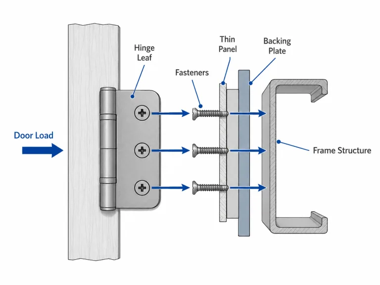
| Опорная конструкция | Резьба, вставки, гайки или арматура могут выдерживать утвержденную зажимную нагрузку | Вырывание резьбы, появление вмятин на панели, отсоединение зажима |
Перед установкой панели проверьте, как петелька сидит на месте, не закрепляя её. Убедитесь, что обе створки соприкасаются с монтажными поверхностями, но при этом не прижимаются винтами до полного прилегания. Если петелька качается при пробной установке, не следует закреплять её силой, затягивая винты; сначала необходимо откорректировать поверхность, расположение отверстий, кронштейн или несущую конструкцию.
Установить одну общую ось шарнира
Именно оси поворота — а не центры монтажных отверстий — определяют, как несколько шарниров с крутящим моментом перемещаются синхронно. Зазор между отверстиями позволяет закрепить два шарнира болтами, даже если их оси смещены, расположены под углом или имеют вертикальный перепад. При повороте панели один шарнир отклоняет другой от его естественной траектории.

Монтажные отверстия служат для фиксации створок; общая точка отсчёта определяет фактическую ось петли.
Используйте базу отсчета, представляющую точку поворота
В зависимости от типа петли и конструкции в качестве ориентира может служить центровочный вал, проходящий через совместимые отверстия, линейка, приложенная к обработанным опорным поверхностям, лазерная линия, специальное приспособление или кронштейн, управляемый системой CAD. Правильным считается тот метод, который позволяет определить фактическую ось поворота без повреждения петли или создания предварительного напряжения в ней.
Не пытайтесь принудительно вращать несоосно расположенную пару
Если панель затягивается только после крепления второго шарнира, остановитесь и проверьте оси. Принудительное перемещение узла в пределах его хода может привести к появлению ложного «высокого крутящего момента», поцарапать поверхности соприкосновения шарниров, деформировать монтажные створки и ускорить локальный износ. Ослабьте крепежные элементы, по возможности снимите внешнюю нагрузку с панели, восстановите совместную ось и определите, какой кронштейн или поверхность смещает петлю.
Если поставщик указывает, что петли представляют собой откалиброванную или подобранную пару, необходимо сохранить эту пару и соблюсти ориентацию при установке. Что касается выбора парных узлов и их влияния на эксплуатационные характеристики, ознакомьтесь с почему для некоторых шарниров с крутящим моментом требуются спаренные пары.
| Наблюдаемое при движении в сухом состоянии | Вероятная причина установки | Мгновенная проверка |
|---|---|---|
| Сопротивление растёт под одним углом | Оси расположены под углом, смещены, либо панель соприкасается с рамой | Слегка ослабьте крепеж и сдвиньте панель, чтобы проверить зазоры |
| Один лист сдвигается при движении | Недостаточное зажатие или нестабильная основа | Отметьте положение листьев и осмотрите несущую конструкцию |
| Одна сторона кажется тяжелее | Погрешность оси, перекос панели или неравномерная регулировка | Проверьте общую систему отсчёта и ориентацию шарнира |
| Панель отклоняется вбок | Скобки или листья заставляют вращаться в разных плоскостях | Проверьте параллельность кронштейнов и плоскостность панелей |
| До окончательной затяжки движение происходит плавно, но после затяжки становится тугим | Изменение последовательности затяжки изменяет положение створки или оси | Проверьте крепление сидений, шайбы, зазор в отверстиях и порядок затяжки |
Управление стопкой крепежных элементов и створок
Крепежные элементы должны удерживать петлю в заданном положении, не деформируя створку, не деформируя монтажную поверхность, не вырывая опорную резьбу и не изменяя выравнивание оси вращения. «Более тугое» затягивание не всегда означает большую надежность.
| Ввод данных о крепежных элементах | Требования к установке | Неудача в случае отсутствия контроля |
|---|---|---|
| Размер крепежного элемента и форма головки | Используйте утвержденный винт или болт, который правильно входит в отверстие петли | Точечная нагрузка, интерференция, неполное прилегание |
| Длина крепежного элемента | Обеспечить полное зацепление без задевания дна в глухом отверстии | Неправильный момент затяжки или повреждение внутренней резьбы |
| Прокладка или опорная поверхность | Используйте только утвержденные значения диаметра стопки и посадочного диаметра | Вдавливание листа, изменение коэффициента трения, снижение устойчивости зажима |
| Состояние нити | Чистый, неповрежденный и совместимый с утвержденным крепежным элементом | Перекрестная нарезка резьбы, срыв резьбы, неплотное затягивание зажима |
| Метод блокировки | При необходимости используйте утвержденный механический фиксатор или резьбовой фиксатор | Сдвиг крепежного элемента или изменение характеристик крутящего момента и натяжения |
| Ужесточение требований | Следуйте чертежу проекта, инструкции по установке петель или утвержденной рабочей инструкции | Повреждение вследствие смещения зажима или чрезмерного затягивания |
| Последовательность затяжки | Постепенно опускайте крепежные элементы, соблюдая совместную ось | Листья перекрывают просветы или скручиваются |
Предупреждение по установке: Не увеличивайте момент затяжки винтов для устранения неплотной панели, неровной опорной поверхности или невыровненной петли. Чрезмерная затяжка может привести к деформации створки, повреждению литого под давлением выступления, вырыванию резьбы из основания или заклиниванию ранее свободно работающего узла.
Последовательность монтажа шарнира Torque из 7 этапов
Следующая последовательность действий позволяет контролировать положение оси шарнира в процессе установки створок, панели и крепежных элементов в окончательное положение. Приведите приспособление и способ доступа в соответствие с утвержденным чертежом шарнира.
- Проверьте выпущенную конфигурацию. Уточните модель петли, количество, ориентацию, сторону открывания или направление крутящего момента, диапазон открывания створки, разрешенные крепежные элементы, а также наличие возможности регулировки петли. Сохраните любую идентификацию пар, установленную поставщиком.
- Подготовьте и проверьте монтажные поверхности. Удалите заусенцы, мусор, отслоившееся покрытие и временные препятствия. Убедитесь, что каждая створка лежит ровно, не удерживаемая на месте винтами.
- Определите общую ось вращения. Используйте утвержденную базу отсчета, центровочный вал, зажимное приспособление, линейку или лазерный ориентир. Не используйте свободные монтажные отверстия в качестве единственного средства контроля выравнивания.
- Временно установите створки со стороны рамы. Соедините крепежные элементы, не затягивая их окончательно. Убедитесь, что створки остаются на месте и их по-прежнему можно регулировать относительно общей оси.
- Установите и закрепите саму панель. Используйте зажимное приспособление или временную опору, чтобы вес панели не привёл к смещению петель во время сборки. Установите створки со стороны панели и проверьте зазоры перед окончательной затяжкой.
- Затягивайте постепенно, проверяя при этом свободу движения. По мере необходимости чередуйте установку петель и крепежных элементов. После завершения каждого этапа продвиньте створку по всему рабочему диапазону и убедитесь, что сопротивление остается равномерным, а створки не смещаются.
- Осуществите настройку и проверьте работу под реальной нагрузкой. В случае регулируемых петель выполняйте настройку небольшими шагами с учетом фактических размеров панели, установленных аксессуаров, кабелей и рабочего центра тяжести. Перед фиксацией узла проведите проверку угла удержания, смещения, зазора, заклинивания и крепежа.
Не используйте шарнир с моментом сопротивления в качестве рычага для притягивания неподпертой панели в конечное положение. Поддерживайте панель до тех пор, пока створки не установятся на место, а крепежные элементы не достигнут требуемого состояния.
Настройка регулируемых моделей после окончательной установки
Регулируемые модели следует настраивать только после полной установки рабочей панели, крепежных элементов, кабелей, уплотнений и принадлежностей. Обеспечьте опору панели, изменяйте настройку небольшими шагами в пределах диапазона, указанного поставщиком, и после каждого изменения перемещайте панель по всему рабочему диапазону. Если две регулируемые петли должны двигаться синхронно, придерживайтесь утвержденного метода парной регулировки, а не изменяйте настройку одной стороны в полном объеме.
Информацию о механизмах регулировки, выборе модели, а также о различиях между регулируемыми и заводскими конфигурациями см. в регулируемая направляющая шарнира с регулировкой крутящего момента.
Не добавляйте при монтаже смазочные материалы, не прошедшие утверждение: Остатки масла, смазки, силиконового спрея, проникающей смазки или чистящего средства могут нарушить заданные условия трения. Наносите смазку только в том случае, если на конкретном чертеже петли или в инструкции поставщика указаны разрешенный продукт, его количество и место нанесения. Прежде чем рассматривать тугое движение петли как проблему со смазкой, проверьте правильность выравнивания или наличие заклинивания.
Провести заключительную функциональную проверку
Успешная установка определяется не только тем, останется ли панель в открытом положении при одной попытке. Готовая конструкция должна сохранять свою ось, плавно перемещаться в пределах требуемого диапазона, обеспечивать приемлемое усилие со стороны пользователя, удерживаться в положениях, заданных проектом, и оставаться устойчивой в ходе краткой проверки установки, предусмотренной проектом.
| Верификация | Как проверить | Сигнализация неисправности |
|---|---|---|
| Сиденья «Лист» | После окончательной затяжки проверьте все края листов и контрольные отметки | Зазор, покачивание, смещение контура или искривление листа |
| Движение по общей оси | Медленно перемещайтесь по всему диапазону, обращая внимание на зазоры между панелями | Сложное положение, смещение боковой панели, изменение зазора |
| Удержание производительности | Установите панель под каждым углом, предусмотренным проектом, с реальной нагрузкой | Мгновенное отклонение, падение или возвратное движение за пределы установленных требований |
| Стабильность в состоянии покоя | Соблюдайте время выдержки, предусмотренное для данного проекта | Прогрессивное смещение, которое не было заметно при беглом осмотре |
| Усилие, прилагаемое пользователем | Проведите оценку по всему диапазону с использованием утвержденных критериев измерения или пользовательских критериев | Чрезмерные усилия, резкие изменения силы, неравномерность движения из стороны в сторону |
| Стабильность крепежа | Проверить контрольные отметки, посадку деталей, а также соответствие требованиям проекта по усилию затяжки или наличие следов затяжки | Вращение, оседание, ослабленная шайба, вмятина в основании |
| Помехи | Осмотрите кабели, уплотнения, защелки, упоры и соседние панели со всех сторон | Трение, натяжение кабеля, уплотнительный валик, смещение защелки |
| Повторная операция | Проведите цикл проверки готовой сборки в соответствии с установленными в проекте требованиями к монтажу | Усиливающийся дрейф, шум, люфт или изменение сопротивления |
Данная заключительная функциональная проверка не является официальным испытанием на количество циклов или долговечность. Она подтверждает лишь то, что утвержденный шарнир был правильно вмонтирован в данную сборку. Требования к долгосрочному снижению крутящего момента и долговечности должны быть отражены в плане валидации продукта.
Симптомы, возникающие во время установки
Время появления симптома помогает определить, привело ли установка к смещению оси, деформации створки или изменению монтажной конструкции.
| Симптом | Когда это происходит | Вероятная причина установки | Направление корректировки |
|---|---|---|---|
| Перед окончательной затяжкой панель удерживается на месте или плавно перемещается, но после этого — нет | Только после того, как крепежные элементы примут окончательное состояние | Деформация створки, смещение оси, сдвиг кронштейна или изменение геометрии створки | Ослабьте крепежные элементы и проверьте посадку, ровность поверхности и последовательность затяжки |
| В одной части диапазона движение становится затрудненным | Под фиксированным углом после установки | Несоосность осей, соприкосновение панелей, натяжение кабеля, помехи со стороны защелки или уплотнителя | Определите сопротивление шарнира отдельно от внешних помех и повторно проверьте совпадение осей |
| Одна сторона начинает двигаться раньше другой | Во время первоначального перемещения панели после сборки | Неравномерная регулировка, перекос панели, смещение оси или смещение створки | Еще раз проверьте соосность пар, общую ось, посадку створок и жесткость панелей |
| Во время проверки монтажа крепежные элементы или створки шарниров смещаются | После кратковременной повторяющейся работы | Недостаточная фиксация, неподходящий способ закрепления, мягкое основание или оседание опоры | Проверьте весь узел, состоящий из крепежного элемента, шайбы, резьбы и опорной прокладки |
Не заменяйте петлю, пока не убедитесь, что во время монтажа не сместились створка, кронштейн, крепеж или основа. Если изначально конструкция прошла эти проверки, но впоследствии утратила удерживающую способность, воспользуйтесь инструкцией, чтобы диагностировать снижение крутящего момента и долгосрочную потерю прочности.
Пример из области композитных материалов: плавная установка перед затяжкой, заклинивание после затяжки
Это смотанный инженерный сценарий, созданный для пояснения логики монтажа. Он не является документацией по проекту заказчика или отчетом об испытаниях продукции.
В крышке машины используются две шарнирные петли с заводской настройкой момента затяжки. Выбранный суммарный момент затяжки соответствует требованиям, и крышка удерживается при отдельной проверке каждой петли. При сборке обе створки устанавливаются по монтажным отверстиям, а винты затягиваются до упора. После этого крышку становится трудно сдвигать в середине диапазона хода, а одна из створок шарнира демонстрирует небольшое перемещение относительно рамы.
В ходе проверки установлено, что монтажные отверстия имеют достаточный зазор для крепления обеих петель болтами, несмотря на то что их оси вращения не совпадают. Кроме того, на одном из кронштейнов рамы под створкой имеется приподнятый край покрытия. При окончательной затяжке болтов эта створка прижимается к поверхности, что смещает её ось вращения и заставляет обе петли вращаться в разных плоскостях.
- Снимите крышку и ослабьте оба набора петель.
- Выровняйте приподнятый край покрытия и убедитесь, что створка полностью прилегает.
- Используйте приспособление, ориентированное на опорные элементы, а не на центры отверстий.
- Поддерживайте крышку, поочередно опуская все крепежные элементы.
- После каждого этапа затяжки перемещайте крышку по всему диапазону хода.
- Примените окончательно утвержденные условия крепления и повторите проверки нагрузки, зазора и времени выдержки.
Для устранения этой проблемы не требуется использование шарниров с более высоким крутящим моментом или смазочных материалов. Эта операция устраняет монтажные искажения и восстанавливает единую ось, благодаря чему выбранные шарниры могут обеспечить предусмотренное сопротивление.
Контрольный список для установки петли с крутящим моментом
| Проверить | Необходимые доказательства установки | Статус «Пропавший без вести» |
|---|---|---|
| Конфигурация шарнира с фиксацией | Модель, количество, ориентация, направление и тип регулировки соответствуют чертежу | Требуется подтверждение со стороны инженерного отдела |
| Установка на опорную поверхность | Листья лежат ровно без усилия застежки | Подготовьте поверхность перед сборкой |
| Общая ось поворота | Определяется с помощью утвержденной системы отсчета, приспособления, вала или аналогичного метода | Требуется выравнивание |
| Опора панели во время сборки | Нагрузка на панель не приводит к смещению петель | Требуется монтажное приспособление |
| Набор крепежных элементов | Утвержденный крепежный элемент, длина, шайба, резьба, способ фиксации и посадка | Требуется рабочая инструкция |
| Поэтапное ужесточение | Ось и движение остаются стабильными на протяжении всей последовательности затяжки | Требуется пересмотр процесса |
| Конструкция с регулируемым шарниром | Скорректировано с учетом реальных показаний панели и в пределах допустимого диапазона | Связанные с конкретным проектом |
| Граница смазки | В зону трения не попали никакие неразрешенные смазочные материалы или чистящие средства | Требуется проверка необходимости очистки или замены |
| Полный диапазон движений | Никаких затруднений, задеваний, боковых смещений или резких изменений сопротивления | Требуется повторная настройка |
| Удержание под заданным углом | Панель соответствует заданным в проекте требованиям к положению и смещению | Требуется проверка выбора или настройки |
| Зазор между панелями и помехи | Зазоры остаются неизменными; кабели, уплотнения, упоры и защелки не зажаты | Требуется корректировка интеграции |
| Крепление и устойчивость створки | Отсутствие смещения контрольных меток, потери опоры или деформации подложки | Требуется проверка крепления |
Окончательные пределы приемки определяются индивидуально для каждого проекта. Предварительные рекомендации по монтажу не заменяют собой инженерную экспертизу выбранного шарнира, утверждение образца реальной сборки или утверждение производственного процесса монтажа, подлежащего контролю.
Окончательное постановление об установке
Установка шарнира с крутящим моментом считается правильной только в том случае, если створки остаются ровными, все оси вращения лежат на одной заданной оси, крепежные элементы обеспечивают соблюдение этой геометрии без повреждения монтажной конструкции, а готовая панель успешно проходит испытания на перемещение и смещение при полной нагрузке. Не следует применять повышенный момент затяжки винтов, принудительное перемещение или смазку для компенсации неустраненной проблемы с геометрией.
Чтобы получить анализ установки с учетом конкретного проекта, пришлите модель шарнира, чертеж панели, информацию о направлении установки, детали крепления, технические характеристики крепежных элементов, диапазон открытия, а также фотографии наблюдаемого перемещения.
Вопросы и ответы
Почему панель фиксируется только после полной затяжки крепежных элементов шарнира?
Заклинивание, возникающее только после окончательной затяжки, обычно свидетельствует о том, что створка сместилась, прогнулась или была прижата к неровной монтажной поверхности. Это также может означать, что последовательность крепления сместилась на один шарнир от общей оси петли. Ослабьте крепежные элементы, проверьте посадку створки и ровность поверхности, восстановите положение оси шарнира и затяните крепеж снова, выполняя затяжку поэтапно и контролируя процесс.
Можно ли совместить монтажные отверстия, если оси шарниров с торсионным зажимом по-прежнему не совпадают?
Да. Проходные отверстия позволяют закрепить обе створки петли болтами даже в том случае, если центры осей вращения смещены, расположены под углом или ступенчато. Определите фактическую ось вращения с помощью утвержденной базы отсчета, приспособления, выравнивающего вала, линейки или аналогичного метода, а не полагайтесь исключительно на центры отверстий.
Нужно ли смазывать шарнир с фиксацией крутящего момента при установке?
Не наносите масло, смазку, силиконовый спрей или проникающую смазку на поверхность трения, за исключением случаев, когда поставщик конкретной петли явно одобрил продукт, его количество и место нанесения. Смазка может изменить заданные условия трения и снизить удерживающий момент. Прежде чем рассматривать тугую или шумную петлю как проблему, связанную со смазкой, необходимо проверить выравнивание, наличие заклинивания или загрязнения.
Следует ли полностью затягивать два шарнира с крутящим моментом по одной стороне за раз?
Как правило, крепежные элементы следует затягивать постепенно, контролируя при этом совпадение оси и зазоры между панелями, однако точная последовательность зависит от типа петли и крепежного приспособления. Полная затяжка одной петли до того, как будет установлена вторая, может привести к смещению узла относительно заданной оси. Следуйте утвержденному монтажному чертежу или рабочей инструкции.
Как следует настроить шарнир с регулируемым крутящим моментом после установки?
Регулировку следует производить при установленной в сборе панели управления, включая стандартные крепежные детали, кабели, уплотнители и другие принадлежности, влияющие на массу или центр тяжести. Регулировку следует производить небольшими шагами в пределах диапазона, установленного поставщиком; после каждого изменения необходимо переместить панель на весь ход и проверить усилие, прилагаемое пользователем, а также устойчивость в положениях, требуемых проектом.

 Русский
  English
  한국어
한국어  Español
  Italiano
  Deutsch
  Français
  Português