Lift-Off Torque Hinge: Principle, Design, Application, and Frontiers
Contemporary precision equipment places demanding requirements on hinges: “concealed, zero backlash, and repeatedly removable.” Traditional hinges often struggle to balance both easy disassembly and reliable positioning.
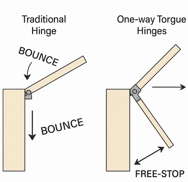
Lift-Off Torque Hinges (LOTH), introduced by manufacturers like HTAN, are a cross-disciplinary solution designed for this purpose. They fuse the “free-stop” characteristic of constant torque hinges with quick-disassembly functionality:
- An internal friction mechanism provides torque, allowing the door panel to remain stationary at any angle without wobbling;
- Simultaneously, the hinge features an axially removable design, enabling direct detachment of the door panel without any tools.
At HTAN, we’ve designed our XG11-070 series torque hinges for both horizontal and vertical installation, and they’ve successfully passed a rigorous 30,000-cycle life test.
This article will comprehensively explore Lift-Off Torque Hinges from Principle → Design → Manufacturing → Application → Trends, providing a one-stop reference for engineers and product managers.
Terminology and Concept Clarification
Lift-Off (Axial Removal)
Refers to the characteristic of a hinge enabling rapid separation by lifting.
Unlike ordinary hinges requiring screw removal, Lift-Off hinges allow the user to simply lift the door or panel, leaving one leaf attached to the door panel and the other to the frame.
Also known as:
- Detachable hinges
- Release hinges
Torque Hinge
Also called a constant torque hinge or position-locking hinge.
It provides constant rotational resistance through an internal friction structure, enabling the door panel to remain stable at any angle.
Key Benefits:
- Eliminates additional supports
- Improves operational convenience
- Prevents door wobbling due to vibration or gravity
Note:
Machine Design magazine states the driving force is constant regardless of hinge angle, and the hinge maintains that angle until moved again.
Distinction from Traditional Hinges
- Traditional Detent Hinges: Lock at fixed angles (e.g., 90°, 180°) via spring detents.
- Standard Lift-Off Hinges: Provide quick removal only; no torque support.
- LOTH: Combines constant torque positioning + tool-free axial removal.
Key Performance Indicators
- Rated torque
- Torque durability decay
- Axial pull-off force
- Life cycle count
- Environmental temperature drift
High-quality hinge benchmarks:
- Torque decay within ±15% after 30,000+ cycles
- Stable performance across -40°C to 85°C
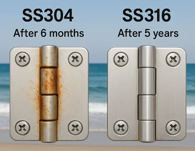
- Corrosion and impact resistance
Deep Dive into Working Principle
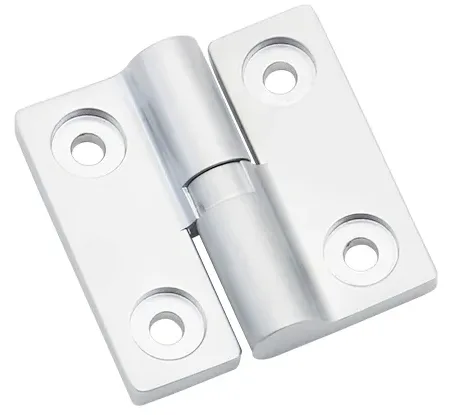
Structural Composition
Male End (Drive Component)
- Contains the central shaft connected to the door
- Features a helical cam surface
- Assembled with a torque mechanism: disc spring stack, wave spring, or friction discs
- Supports torque generation and axial lift-off
Female End (Driven Component)
- Sleeve component fixed to the frame
- Contains helical grooves complementary to the male end
- Includes a spring-loaded locking mechanism (e.g., ball detents)
Torque Generation Mechanism
Torque is produced via:
- Spring preload +
- Helical wedge surface (geometry) → converting axial load into rotational resistance
Simplified formula:T ≈ kμF_preload × r_spiral
Where:
μ: friction coefficientF_preload: spring forcer_spiral: spiral radiusk: efficiency coefficient
Friction Material Pairings:
- Stainless steel + PEEK/MoS₂/PTFE
- All-metal pairs
Note: NASA studies show PEEK composites with PTFE and MoS₂ offer excellent durability and low friction.
Lift-Off Triggering Process
- During use: Male cam and female groove remain engaged, offering constant torque
- For removal: Axial pull force disengages the locking ball → hinge separates
- Enables tool-free panel removal
Mechanical Model
- Treat as coupled axial force + torque problem
- Use simplified torque models and validate via multi-body simulation (e.g., Adams)
Materials and Manufacturing Processes
High-Strength Lightweight Material Matrix
| Component | Material Example | Features |
|---|---|---|
| Shaft Core | 17-4PH Stainless Steel / Ti-6Al-4V | High strength + corrosion resistance / high specific strength |
| Friction Discs | PEEK + MoS₂/PTFE / LCP + PTFE | Low friction, high wear resistance |
Precision Machining Chain
- 5-Axis Milling: For helical cams, ≤0.01 mm contour accuracy
- Surface Hardening:
- DLC on titanium (Hv >2000)
- Nitriding for steel parts
Micro-Assembly and Preload Control
- Disc Springs: Grouped by precise preload tolerance (±2 N·mm)
- Automated Assembly: Laser torque calibration ensures precision
Design for Manufacturability (DFM) Pitfalls
- Ensure helix surface has enough draft angle
- Deburr locking ball holes
- Use temperature-compensation grooves
- Involve process team early to avoid redesign
Performance Testing and Standards
- Torque-Angle Curve: Must stay ±5% from rated torque
- Axial Pull-Off Force: Test via ISO 81346-10 style methods
- Life Cycle Testing:
- Goal: Torque decay <15% after 20,000–30,000 cycles
- Environmental Reliability:
- Temperature (-40°C to 85°C)
- Salt spray (96 hours)
- Drop/shock tests (1 meter)
- Failure Mode Analysis (FMA):
- Torque decay
- Locking ball jamming
- Disc spring fatigue
- Surface coating delamination
Cross-Industry Application Cases
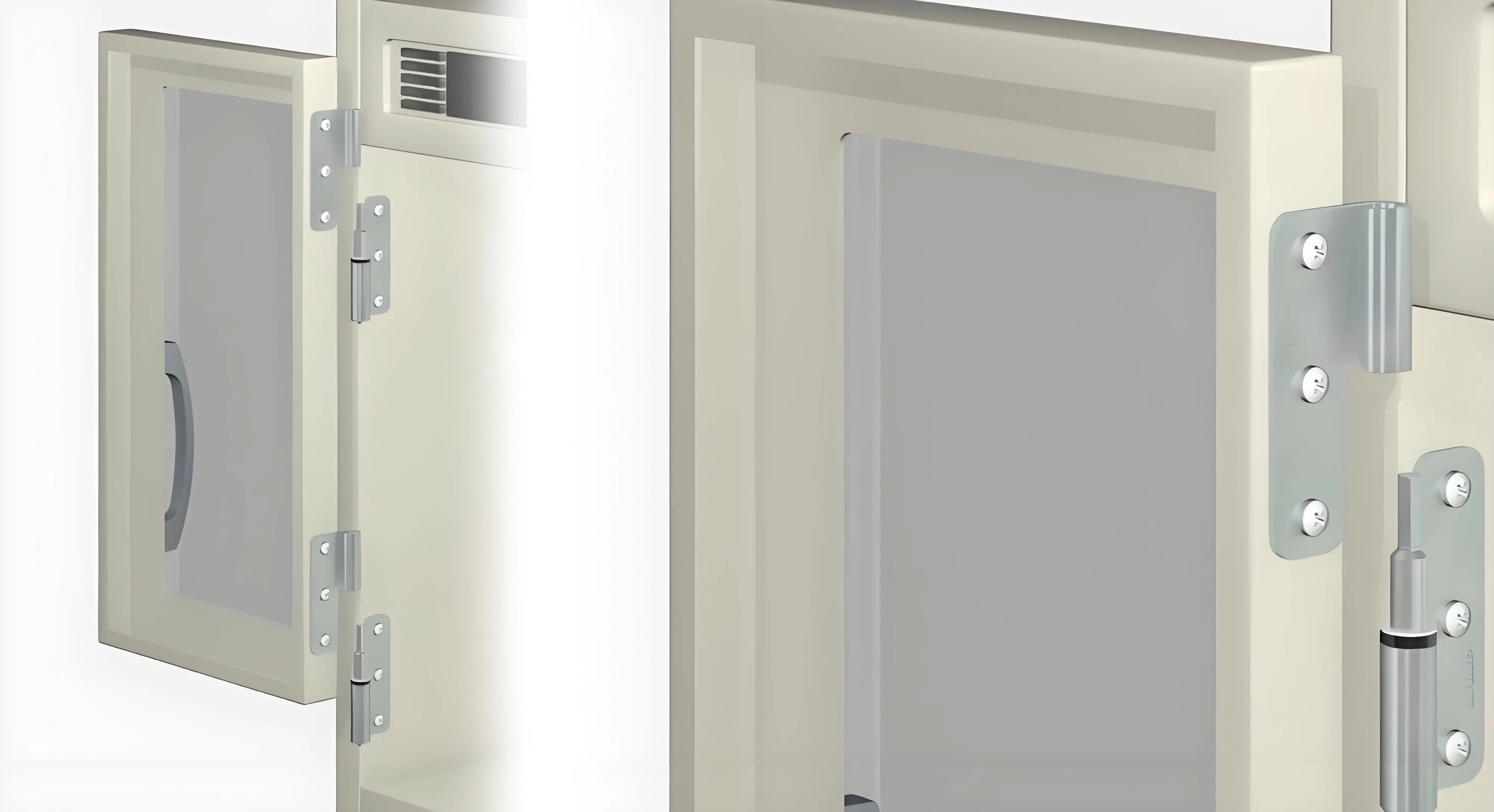
Image source: Sugatsune
Consumer Electronics
- Foldable Smartphones:
- Torque: 0.35 N·m
- Thickness: 2.1 mm
- 50,000-cycle drop-tested
Medical Devices
- Ultrasound Probe Holders:
- Tool-free disassembly
- 0.8 N·m torque
- Medical-grade materials
Automotive Electronics
- Flip-Up Screens:
- High-temp stability (up to 85°C)
- NVH vibration standard compliance
Aerospace
- Satellite Solar Panels:
- Torque ~3 N·m
- 35% weight savings vs. traditional locks
Industrial Automation
- Robot Teach Pendant Holders:
- IP54 sealing
- Quick disconnect with stable positioning
Design Guide and Selection Tools
Torque Calculation
T = kμF_pre r_spiral
Validated via FEA or simulation
Life Estimation
- Use Palmgren–Miner damage theory
- Combine with Archard wear model
- Include S-N fatigue curves
Quick Selection Table
| Load Level | Torque Range | Application Examples |
|---|---|---|
| Light | 0.1–0.5 N·m | Phones, wearables |
| Medium | 0.5–2.0 N·m | Medical mounts, in-car displays |
| Heavy | 2.0–10.0 N·m | Industrial machinery, aerospace mechanisms |
Tolerance Stack-Up & Temperature Compensation
- Temperature drift ~2–3% per 10°C
- Use symmetrical structures or compensation grooves
Common Design Pitfalls
- Oversized helix angle → Self-lock
- Weak spring → Accidental release
- Uneven disc spring preload → Torque imbalance
Simulation and Optimization
- Multi-body Dynamics: Simulate helix-friction interaction (MSC Adams)
- Thermo-mechanical Analysis: Model torque drift at high temp (ANSYS)
- Topology Optimization: Lightweight the sleeve by >20%
- Digital Twins: LSTM models trained on life-cycle torque decay data
Conclusion
The Lift-Off Torque Hinge (LOTH) bridges the market gap between:
- High-reliability quick-release hinges
- Constant torque positioning structures
It offers:
- Tool-free detachment
- Free-stop torque positioning
As manufacturing becomes standardized and cost-effective, LOTH is poised for rapid growth in consumer IoT and portable tech.
Future R&D should focus on:
- Creating industry standards
- Building cross-industry LOTH tech databases
- Promoting the shift from custom to standard components
FAQ
What is a Lift-Off Torque Hinge (LOTH)?
A hinge that combines constant torque with axial quick-disassembly. It holds any angle and allows tool-free removal by lifting.
How does LOTH differ from a standard Torque Hinge?
Standard torque hinges don’t support easy removal—LOTH does. It separates automatically with axial force, no tools required.
What are key considerations when designing LOTH?
- Match helical cam geometry with spring preload
- Ensure locking ball spring strength is optimized
- Maintain strict machining tolerances
- Avoid burrs and ensure surface hardness