5 Common Mistakes with Torque Hinges — and How to Avoid Them
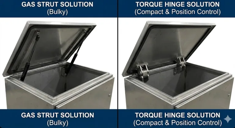
Torque hinges generate controlled resistance through internal friction mechanisms, enabling door panels or covers to remain fixed at any angle. Widely used in industrial equipment, electronic enclosures, cabinet doors, and similar applications, they maintain stable positioning for covers and displays without requiring gas springs or support brackets. However, many engineers make mistakes during torque selection, installation, and maintenance, leading to sagging panels, breakage, or safety hazards. This article analyzes the five most common errors and provides practical solutions.
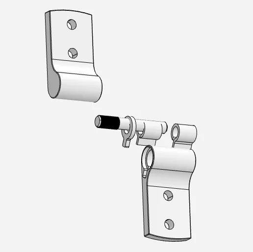
Sectional View of Torque Hinge Structure
Before delving into specific errors, understanding the torque hinge’s operating principle is essential. Typically composed of a hinge shaft tube and pivot, the shaft tube houses mechanisms including springs, friction plates, and damping elements. When the panel opens or closes, these internal components slide relative to each other, generating friction that produces a predetermined torque. This torque enables the panel to remain stationary at any desired position. Based on mechanical principles, the required torque can be calculated using the following equation:
M = F × d × cos θWhere F is the panel’s gravitational force (mass × gravitational acceleration g ≈ 9.81 m/s²), d is the horizontal distance from the panel’s center of gravity to the hinge axis, and θ is the angle between the panel and the horizontal plane.
Error 1: Incorrect Torque Range Selection
Issue
Torque requirements are inaccurately calculated during selection, often underestimated or overestimated.
Consequences
Insufficient torque prevents the panel from holding at the desired position, causing it to slowly sag or even slam shut unexpectedly. Excessive torque makes the panel difficult to open or close, leading to user operation difficulties. Both conditions increase the risk of malfunction and potential safety hazards.
Technical Note
Torque must counteract the panel’s moment. For a 5 kg panel with a width of 400 mm and center of gravity on the centerline, gravitational force is F = 5 × 9.81 = 49.05 N, with a distance from the hinge axis of d = 0.2 m. Neglecting angular variation (θ=0°), the required torque is:
M = 49.05 × 0.2 = 9.81 N·mApplying a 20% safety margin:
Mₑ = 9.81 × 1.2 ≈ 11.8 N·mTherefore, a hinge model with a rated torque of approximately 12 N·m should be selected to ensure stable panel positioning across the full range of angles.
Solution
- Calculate torque precisely. First, accurately measure the panel’s weight and dimensions, determine its center of gravity, and compute the required torque using the formula M = F × d × cosθ.
- Distribute the load. For heavier or wider panels, use two or more torque hinges in parallel. Ideally, each hinge shares the total torque equally, but installation errors and panel deformation may cause deviations. Calculate the maximum torque per hinge based on the worst-case scenario (e.g., 60%/40% distribution) to enhance reliability.
- Incorporate a margin. Add approximately 20% to the calculated result to account for dynamic loads and manufacturing tolerances.
- Avoid relying solely on intuition or analogies from other projects. Select appropriate models based on measured data and calculations.
Error 2: Neglecting Environmental Factors
Issue
Failure to choose suitable materials or protection ratings based on the operating environment.
Consequences
Hinges may rust or oxidize in humid, saline, or chemically corrosive environments, leading to reduced friction or even jamming that compromises panel retention. Extreme temperatures may cause material aging or deformation, shortening hinge lifespan.
Recommended Measures
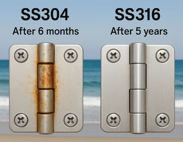
- Select corrosion-resistant materials. In humid or chemical environments (e.g., marine, chemical processing), prioritize corrosion-resistant materials like 316L stainless steel. For standard indoor environments, lower-cost zinc alloy or standard steel hinges may be used.
- Surface Treatment. For aluminum alloy components, anodizing per ISO 7599:2018 can form a dense protective layer; zinc alloy hinges may undergo nickel or chrome plating to enhance corrosion resistance.
- For corrosive environments, verify materials and coatings in accordance with ASTM B117-19 (Salt Spray Test) and request official compliance test reports from the supplier. For sealing performance, conduct design verification and factory inspections based on the IEC 60529 IP rating standard.
- Integrated Design. Where necessary, employ sealed hinges (with rubber or plastic seals) to protect internal friction mechanisms. To meet specific application requirements, consider solutions such as salt spray resistance, electroplated high-gloss finishes, or special alloys (e.g., nickel-plated carbon steel alloys).
Error 3: Improper Installation and Alignment
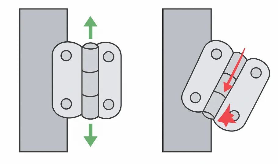
Incorrect Installation and Alignment Diagram of Torque Hinge
Issue
Hinge mounting positions are non-parallel or misaligned, causing uneven stress distribution or mechanical interference.
Symptoms
Hinge may exhibit uneven wear, looseness, abnormal noise, or even jamming. Panel feels noticeably heavier on one side when opened, with unstable friction and reduced holding force.
Solutions
- Ensure panel is flat. Mounting surface must be solid and parallel. Use positioning jigs or templates to align mounting holes for each hinge, avoiding deviations exceeding half a degree.
- Calibrate alignment. Mark installation lines. After pre-installing fasteners, suspend the panel and meticulously verify that the hinge axis and panel center of gravity lie within the same vertical plane. Adjust before securing screws.
- Apply appropriate torque. Fasten screws moderately. Use a torque wrench to tighten to the manufacturer’s specified torque value to prevent excessive torque from deforming the hinge base or panel.
- Functional Testing. After installation, manually or mechanically move the panel through its full range of motion to verify smooth operation without scraping. Immediately disassemble and adjust if any sticking or uneven movement occurs.
Mistake 4: Improper Maintenance—Using Lubricants
Issue
Incorrectly applying lubricating oils or greases to “extend lifespan.”
Consequences
Lubricants can penetrate the friction mechanism, degrade internal friction surfaces, and eventually cause torque loss or hinge failure. Penetrating lubricants like WD-40, motor oil, or silicone oil are especially hazardous, leading to deposits and adhesion.
Note
Some adjustable or specialized torque hinges may permit manufacturer-specified dry film lubricants or solid lubricants. Strictly follow the manufacturer’s maintenance manual.
Solution
- Prohibit lubrication. Eliminate all oily or greasy lubricants; spraying WD-40, silicone oil, motor oil, etc., on torque hinges is strictly forbidden.
- Dry wipe cleaning. Use only a clean soft cloth or paper towel to remove surface dust. If necessary, use a small brush to clear particles around rivets.
- Regular Replacement. As opening/closing cycles increase, friction components inevitably wear. When significant torque loss or hinge looseness occurs, replace the hinge immediately. Do not attempt to restore functionality through lubrication.
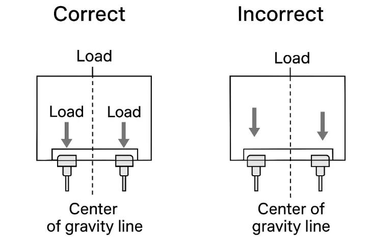
Mistake 5: Neglecting Design Integration and Load Distribution
Issue
Treating torque hinges as ordinary components without incorporating them into overall structural and stress analysis.
Consequences
Uneven load distribution or stress concentration on hinges. Concentrating panel weight on a single hinge risks overload failure or panel sagging. Additionally, misalignment between the hinge axis and the center of gravity generates additional bending moments, leading to premature fatigue damage.
Recommended Solution
- Distribute multiple hinges evenly. Based on panel size and weight, use at least two hinges in parallel to share the torque load. Ensure identical force geometry for each hinge to prevent any single hinge from bearing the primary torque load.
- Align Axis with Center of Gravity. During CAD design, maintain the hinge rotation axis and the panel’s center of gravity (center hole) within the same vertical plane. This allows torque forces caused by gravity to be synchronously counteracted by all hinges. Failure to account for center of gravity distribution may lead to premature hinge wear.
- Perform mechanical analysis and validation. Use simulation software to analyze torque distribution. Conduct prototype testing when necessary. Adjust the number and position of hinges to ensure smooth opening/closing action and balanced force distribution across all hinges.
- Pay attention to mounting positions. Hinges spaced too closely or too far apart will affect load-bearing effectiveness. Overcrowding may cause insufficient load capacity at mounting holes, while excessive spacing may cause sagging in the middle panel area. Designs should incorporate reasonable hinge spacing or add intermediate supports.
Common Errors and Solutions
| Error Type | Potential Consequences | Preventive Measures |
|---|---|---|
| Improper torque range selection | Panel fails to secure/sudden drop; Difficulty opening/closing due to excessive torque | Calculate torque precisely with safety margin; distribute load across multiple hinges; select models cautiously. |
| Neglecting environmental factors | Hinge corrosion/rust, reduced friction, or jamming | Use corrosion-resistant materials like 316L stainless steel; apply zinc-aluminum alloy surface anodization or plating; select products meeting ASTM B117/IP standards. |
| Improper installation alignment | Unstable movement, abnormal noise, weakened holding force | Ensure installation surfaces are level; use alignment fixtures for positioning; tighten screws to manufacturer’s torque specifications; conduct full-range testing and adjustments post-installation. |
| Misuse of lubricants | Loss of torque function, hinge failure | Prohibit use of penetrating oils like WD-40; Clean only with a dry cloth; replace hinges directly when torque decreases. |
| Insufficient Design Integration | Hinge breakage, panel sagging, or stress concentration | Consider panel center of gravity and torque distribution during design; parallel multiple hinges to distribute torque; perform CAD analysis and prototype testing; ensure proper hinge mounting positions. |
Best Practices for Torque Hinge Selection and Maintenance
- Define requirement parameters: Determine panel weight, dimensions, and opening angle range before selection to calculate torque.
- Calculate torque with margin: Use formula M=F×d×cosθ to determine required torque, adding approximately 20% safety factor. For dual hinges, torque values may be evenly distributed.
- Select High-Performance Materials: Choose appropriate materials based on the operating environment. For example:
- 316L stainless steel offers superior corrosion resistance.
- Zinc alloy provides high strength and low cost, with corrosion resistance enhanced through plating.
- Aluminum alloy treated with ISO 7599 standard anodization combines aesthetic appeal with protective functionality.
- Strict installation control: During installation, ensure the hinge bracket is flush and aligned with the panel mounting surface. Use screws of the correct specification and tighten to the recommended torque. Employ positioning fixtures and torque wrenches to enhance installation precision.
- Regular inspection and replacement: Over time, friction components in hinges wear down, gradually reducing torque. Regularly inspect hinge rotation smoothness and holding force. Replace severely worn hinges promptly to ensure reliability.
Conclusion: Enhancing Industrial Equipment Safety and Reliability
Torque hinges are critical motion control components in industrial machinery. Proper selection, precise installation, and adequate maintenance ensure long-term stable positioning functionality. Action recommendations:
- Inspect existing equipment: Identify torque hinges with insufficient torque, wear, or looseness, adjusting or replacing them as necessary. During selection, request suppliers to provide rated torque test curves, tolerance specifications, and lifespan validation data (e.g., cycle life ≥20,000 cycles, tolerance ±15%) to ensure performance meets long-term operational requirements.
- Incorporate torque analysis during design: During equipment design and simulation, calculate panel moments and verify torque hinge positions and quantities to prevent future maintenance.
- Consult professional suppliers: Collaborate with torque hinge manufacturers or suppliers to obtain technical support and suitable products.
Proper selection and maintenance of torque hinges significantly enhance equipment safety and service life, making industrial machinery more durable and efficient.
Proper selection and maintenance of torque hinges ensure safer, longer-lasting, and more efficient industrial equipment performance.
Frequently Asked Questions (FAQ)
Q1: What distinguishes torque hinges from standard hinges?
Torque hinges (also known as friction hinges) incorporate an internal friction mechanism that generates resistance during opening, allowing panels to be secured at any position. Standard hinges provide only rotational movement without self-locking capability, preventing panels from maintaining specific angles solely through the hinge mechanism.
Q2: How do I calculate the required torque for my equipment?
Torque can be calculated using the following formula:
M = F × d × cosθWhere:
- F – Gravitational force on the panel (mass × gravitational acceleration, g ≈ 9.81 m/s²)
- d is the horizontal distance from the panel’s center of gravity to the hinge axis (unit: m);
- θ is the angle between the panel and the horizontal plane. When θ = 90° (panel vertical), cosθ = 0, thus no holding torque is generated.
After calculating the total torque, divide the result by the number of hinges and add a safety margin of approximately 10%–20%.
Example:
Panel weight: 5 kg, width: 400 mm, center of gravity located on the centerline, with one hinge installed on each side.
Calculation process:
F = 5 × 9.81 = 49.05 N
d = 0.2 m
Total torque M = 49.05 × 0.2 = 9.81 N·m
Torque per hinge = 9.81 ÷ 2 = 4.9 N·m
After accounting for a 10%–20% margin, select hinges rated for 5.5–6 N·m torque.
If installation deviations or uneven loads exist, verify under the most unfavorable condition where a single hinge bears 60% of total torque to ensure stable panel positioning at any angle.
Q3: Can torque hinges be lubricated?
No. Lubricants can penetrate the friction mechanism, damaging the internal friction layer and rendering the torque function ineffective. Avoid using WD-40, motor oil, silicone oil, or similar lubricants. Wipe surfaces only with a dry cloth. Replace the hinge if torque performance significantly declines.
Q4: What materials are commonly used for torque hinges in industrial equipment?
- 316L Stainless Steel: High corrosion resistance, suitable for demanding environments like outdoor applications and medical equipment.
- Zinc Alloy: Low cost and high cost-effectiveness, suitable for general indoor equipment. Surfaces can be nickel-plated or phosphated to enhance corrosion resistance.
- Aluminum Alloy: Lightweight with high strength. Anodized finishes provide both aesthetic appeal and corrosion resistance, commonly used in control panels and display mounts.
Q5: What should I do if my cover plate still fails to hold its open position?
Possible causes include: insufficient torque rating; misaligned hinge installation; worn-out hinge failure. Recommendations: recalculate required torque and select a higher-torque model; verify hinge mounting alignment; replace with new hinges if aged.
Q6: What is the typical lifespan of a torque hinge?
Longevity depends on materials, manufacturing processes, and operating conditions. Low-end products may last only a few hundred cycles, while high-quality torque hinges can withstand tens of thousands of cycles in testing. Some hinges with patented friction mechanisms achieve lifespans exceeding 50,000 cycles. Regularly inspect rotational smoothness and holding force, replacing hinges promptly upon performance degradation.
Q7: Are adjustable torque hinges worth choosing?
Yes. In practical applications, panel weight or usage requirements may change over time. Adjustable hinges allow users to fine-tune torque settings post-installation, offering broader applicability (e.g., in testing equipment, display mounts, etc.). While their structure is slightly more complex and cost is marginally higher, they significantly enhance flexibility and maintenance convenience.