How to Calculate Hinge Torque: A Step-by-Step Guide
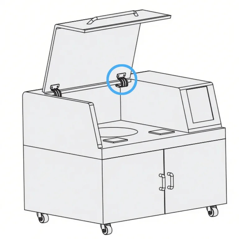
Hinge torque is a critical parameter in designing rotating covers, door panels, or displays. It determines the damping effect and balance as components open and close. Incorrect torque design can cause panels to fall uncontrollably, make opening difficult, or lead to safety incidents. Understanding torque calculation is essential for enhancing product safety and user experience.
This article begins with the physical definition of torque, systematically analyzes influencing factors and calculation formulas, and demonstrates the process through practical examples. This article covers the definition of torque, key variables, calculation examples, safety factors, and verification methods, enabling designers to quickly grasp the essential principles.
Core Functions of Hinge Torque
Support and Damping
Hinges bear the weight of the panel and provide resistance during opening, ensuring stability at any angle.
Balance and Safety
Proper torque allows a panel to open in a balanced manner, preventing it from dropping suddenly under its own weight. Insufficient torque creates a falling risk, while excessive torque makes opening difficult and can cause stress concentration.
Enhanced Operability
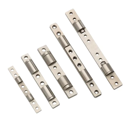
Torque hinges (or “friction hinges”) enable free-stop positioning at any angle without additional support mechanisms.
Objective
This article progressively demonstrates the definition, calculation formula, and design process for hinge torque. It includes: defining the calculation formula, providing step-by-step examples, introducing safety factor adjustments, and detailing verification methods. Finally, it offers torque selection references for various application scenarios, empowering engineers to master hinge torque design.
Understanding the Fundamentals: What is Hinge Torque?
Definition and Calculation of Hinge Torque
Physical Definition
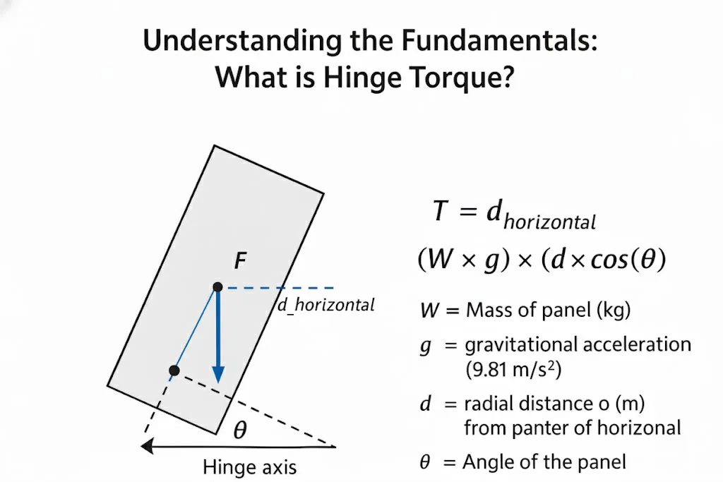
Torque ($T$) is the rotational force, defined as the applied force ($F$) multiplied by the lever arm length ($d$). For a hinge, the primary force is the panel’s weight (Mass $\times$ Gravitational Acceleration) acting at its center of gravity. Torque is commonly measured in N·m (Newton-meters).
The fundamental formula is expressed as:
$T = F \times d_{\text{horizontal}} = (W \times g) \times (d \times \cos(\theta))$
Where:
- $W$ = Mass of the panel (kg)
- $g$ = Gravitational acceleration (≈9.81 m/s²)
- $d$ = The radial distance (straight-line distance) from the panel’s center of gravity to the hinge axis (m)
- $d_{\text{horizontal}}$ = The horizontal lever arm (m), which is the component of $d$ that actually produces torque. It is calculated as $d_{\text{horizontal}} = d \times \cos(\theta)$
- $\theta$ = The angle of the panel relative to the horizontal plane.
- The fundamental formula is expressed as:
T=F×dhorizontal=(W×g)×(d×cos(θ))T = F \times d_{\text{horizontal}} = (W \times g) \times (d \times \cos(\theta))T=F×dhorizontal=(W×g)×(d×cos(θ))
This formula correctly shows that Torque is MAXIMUM ($T = Wgd$) when the panel is horizontal ($\theta = 0°$), as the lever arm is longest. Torque becomes ZERO when the panel is vertical ($\theta = 90°$), because the line of action of the panel weight passes through the hinge axis and the lever arm is effectively zero.
Static Torque vs. Dynamic Torque
- Static Torque: The rotational force required to hold the panel stationary at a specific angle (overcoming gravity). This is the primary focus of our calculation.
- Dynamic Torque: The additional torque needed to overcome inertia (to start or stop motion) and damping forces.
Design typically focuses on calculating the maximum static torque first, then considers dynamic effects based on the application.
Functional Role in Design
Hinge torque controls the panel’s balance, enables free-stop positioning, and prevents sudden closure. For example, torque hinges use internal friction mechanisms to hold covers stationary. Proper torque ensures stable, smooth operation.
Key Factors Affecting Hinge Torque
Cover Weight (W): Torque is directly proportional to the panel’s weight.
Center of Gravity (d): The greater the horizontal distance (lever arm) from the panel’s center of gravity to the hinge axis, the higher the required torque. For asymmetrical panels, the actual center of gravity must be determined.
Number of Hinges (N): Multiple hinges share the total torque load. For a symmetrical layout, the total torque is ideally distributed evenly: $T_{\text{per_hinge}} = T_{\text{max}} / N$ (Assumes symmetrical load distribution. For asymmetrical panels where the center of gravity is not centered between the hinges, the total torque ($T_{\text{max}}$) is still the target. However, designers must ensure the panel is sufficiently rigid to prevent racking or twisting during operation.)
Installation Angle and Rotation Range ($\theta$): Torque is maximum when the panel is horizontal ($\theta = 0°$) and minimum (zero) when vertical ($\theta = 90°$). Design calculations must always use the maximum torque scenario (the horizontal position) as the basis.
Damping and Friction: Internal friction in torque hinges provides the “holding” force. Environmental factors such as temperature, dust, or lubrication conditions can affect actual torque. High temperatures may reduce damping grease viscosity (lowering torque), while low temperatures or contamination may increase friction(Laesecke et al., 2019, NIST).
Formula Calculation and Step Analysis
Basic Formula
The fundamental hinge torque calculation is:
$T = W \times g \times d \times \cos(\theta)$
For design purposes, we must find the maximum torque ($T_{\text{max}}$), which occurs when the panel is horizontal ($\theta = 0°$, which means $\cos(0°) = 1$).
The formula simplifies to:
$T_{\text{max}} = W \times g \times d$
A hinge supplier’s selection reference formula, such as “Torque $T = L/2 \times m \times 9.8$ (in N·m)”, is based on this exact principle. It assumes:
- $m$ = mass ($W$)
- $L/2$ = center of gravity distance ($d$), assuming a uniform panel where the C.G. is at half its length/width.
Example: For a panel with $L=0.3$ m (so $d=0.15$ m) and $m=2$ kg, the maximum torque is:
$T_{\text{max}} = 0.15 \text{ m} \times 2 \text{ kg} \times 9.81 \text{ m/s}^2 \approx 2.94$ N·m.
Calculation Steps
Step One: Calculate Total Maximum Torque ($T_{\text{max}}$)
Always use the formula for the horizontal position ($T_{\text{max}} = Wgd$) to find the worst-case load.
Example: A panel has a mass ($W$) of 8 kg, and its center of gravity ($d$) is 0.25 m from the hinge axis.
$T_{\text{max}} = W \times g \times d$
$T_{\text{max}} = 8 \text{ kg} \times 9.81 \text{ m/s}^2 \times 0.25 \text{ m} \approx$ 19.62 N·m
This 19.62 N·m is the total static torque the hinge system must be able to support to hold the panel in its heaviest position (horizontal).
Step Two: Hinge Torque Distribution
Calculation Steps: Hinge Torque Distribution (Symmetrical Load)
If using multiple hinges, divide the total maximum torque by the number of hinges ($N$).
In the example above, if using $N=2$ hinges:
$T_{\text{per_hinge}} = T_{\text{max}} / N = 19.62 / 2 \approx$ 9.81 N·m per hinge.
You would then select two hinges rated for at least 9.81 N·m, after applying safety factors.
Correction and Safety Factor Considerations
- Safety Factor: Safety Factor: Multiply $T_{\text{max}}$ by 1.2–1.5 to account for assembly errors, material aging, and manufacturing tolerances. For rapid motion or high-vibration environments, add an additional 10–30% margin. In extreme temperatures, consult manufacturer data for torque variation due to damping grease viscosity changes.
- Dynamic Load Correction: For rapid opening/closing, or in high-vibration environments (like vehicles), add an additional 10–30% margin.
- Temperature and Friction Effects: For extreme environments, consult manufacturer data on how temperature affects the hinge’s torque rating.
- Support Mechanism Correction: If the system has assists (e.g., gas springs, torsion springs), the assist torque can be subtracted from the total torque. $T_{\text{hinge}} = T_{\text{max}} – T_{\text{assist}}$.
Design Verification and Debugging
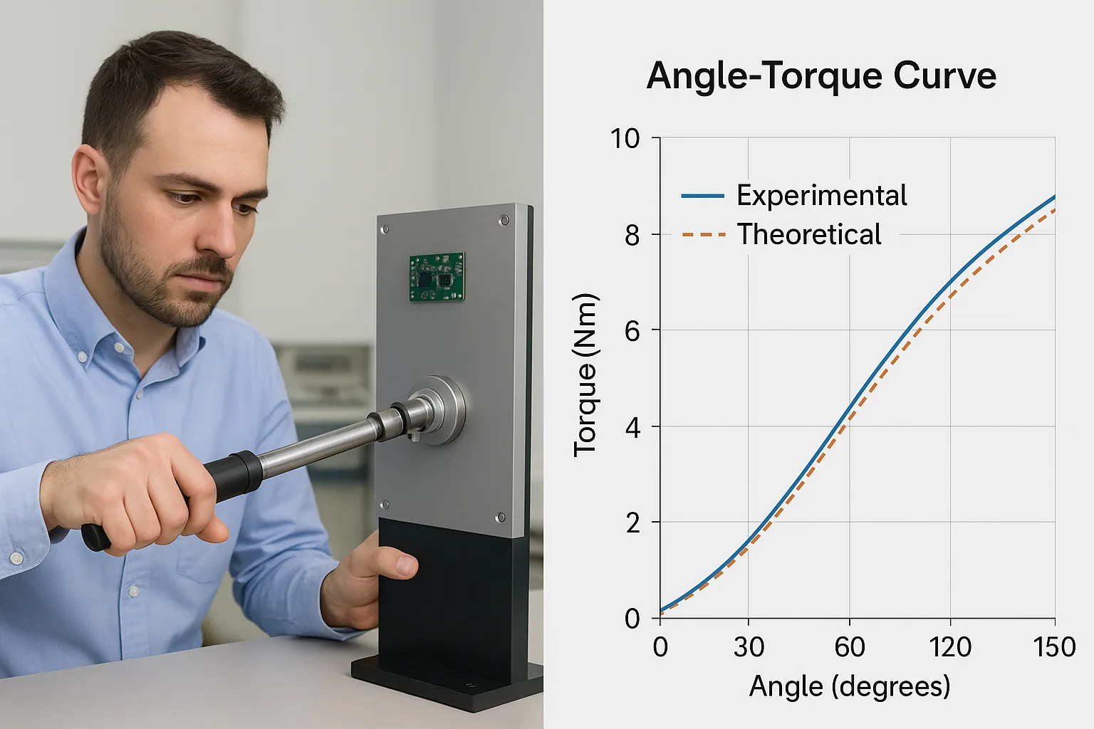
Torque Hinge Performance Test and Angle–Torque Curve
- Experimental Validation: Use a torque wrench on a prototype to measure the actual opening/closing force at multiple angles, especially if free-stop positioning is required. Compare empirical results with calculated values to ensure design accuracy.
- Software Simulation: Use CAD and motion analysis software to simulate the opening cycle and visualize the angle-torque curve.
- Debugging and Optimization: If opening resistance is too high, consider reducing hinge friction or repositioning the center of gravity. If the panel sags, you must increase the hinge torque rating.
Torque Design Guidelines for Different Applications
- Industrial Equipment Covers: Prioritizes high torque and durability for frequent use and secure latching.
- Medical Device Displays: Emphasizes smooth, precise positioning and a consistent feel. Often uses precision torque hinges with tight tolerances (e.g., ±20%).
- Vehicle Doors and Access Panels: Must account for high vibration and impact, often requiring compliance with specific automotive standards(SAE J934_2019).
- Electronic Enclosures (e.g., Laptop Hinges): Requires high-cycle life, miniaturization, and extremely consistent torque in a small package.
Key Design Principles and Summary
- Core Parameters: The design is driven by panel weight ($W$), center-of-gravity distance ($d$), and the number of hinges ($N$).
- Formula and Modifications: Calculate the maximum static torque using $T_{\text{max}} = Wgd$ (for the horizontal position). Apply a safety factor (1.2–1.5) and any dynamic/environmental corrections.
- Verification: Always validate your calculations with a physical prototype or accurate simulation.
- Free-Stop Positioning: If the design requires holding a position at any angle, specify torque hinges (friction hinges). These provide constant resistance to enable “touch-to-stop” functionality.
By systematically calculating and validating, engineers can ensure hinge torque both fulfills product functionality and incorporates necessary safety margins.
Appendix
A. Torque Unit Conversion Table
| Unit | Conversion |
|---|---|
| N·m | 1 N·m = 10.197 kgf·cm = 8.851 lbf·in |
| kgf·cm | 1 kgf·cm = 0.09807 N·m |
| lbf·in | 1 lbf·in = 0.11298 N·m |
B. Reference Torque Ranges for Common Hinges
| Application Scenario | Common Torque Range (Total) |
|---|---|
| Small Electronic Devices | 0.1–2 N·m |
| Medical/Instrument Displays | 1–5 N·m |
| Industrial Cabinets | 5–20 N·m |
| Heavy-Duty Machinery Hatches | 20–50 N·m (and above) |