
Bullet Hinge Strength Guide: How to Calculate Weight Capacity for Gates & Doors
The Industrial Standard for Weld-on Security: Engineering Selection & Load Dynamics
Defining the Bullet Hinge
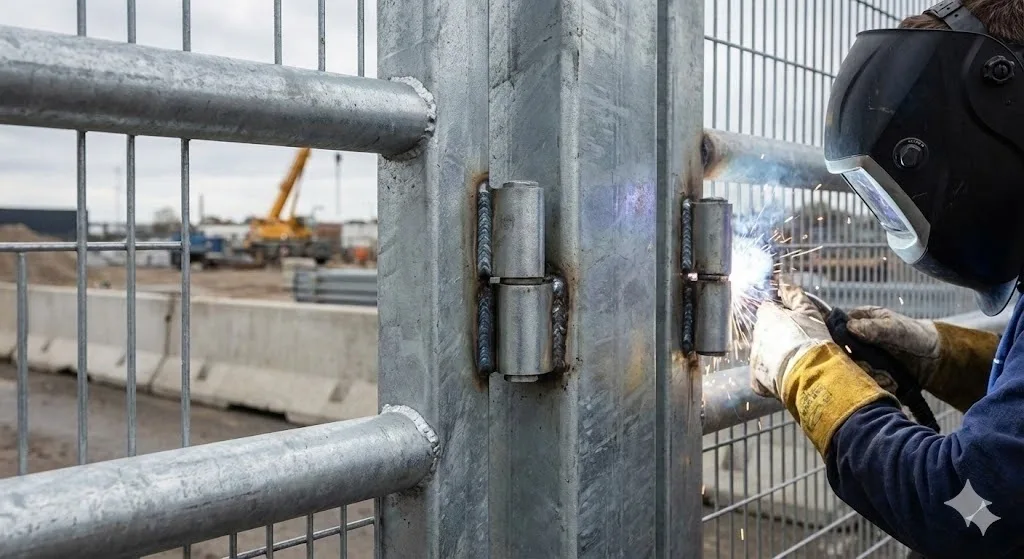
A bullet hinge, also referred to as a weld-on hinge, is a two-part mechanical pivot consisting of a male component (with a pin) and a female component (the barrel). In industrial engineering, these hinges are preferred for their streamlined profile and the security provided by permanent welding. Unlike bolt-on hinges, bullet hinges eliminate the risk of fasteners loosening over time due to vibration or thermal expansion.
Why Load Calculation Matters: Ensuring IP Integrity
Accurate load estimation is the technical foundation for the longevity of any industrial enclosure. Inadequate calculation leads to door sagging, which compromises the seal of gaskets and lowers the Ingress Protection (IP) rating of the cabinet. Following EN 1935 standards for single-axis hinges (Grades 11-14 for heavy-duty applications), engineers must account for both the mass of the door and the mechanical torque (radial stress) exerted during operation.
Versatility in Application
These hinges are utilized across a spectrum of B2B sectors, including:
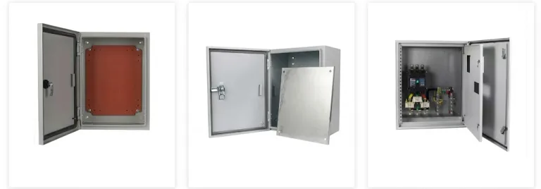
- Electrical control cabinets (IP65/IP66 compliance).
- Specialized medical equipment housings.
- Heavy-duty industrial gates and access panels.
- Modular data center frames.
Anatomy of a Bullet Hinge: Designed for Durability
The Male and Female Components
The precision fit between the pin (male) and the barrel (female) determines the radial play of the door. A high-quality bullet hinge maintains tight tolerances to ensure that the door remains aligned throughout its service life.
The Internal Washer: Reducing Axial Friction
A critical but often overlooked component is the internal washer, typically made of brass or stainless steel. This washer sits between the two barrels to:
Mitigate Axial Stress: Prevent direct metal-on-metal grinding (galling) between the weldable surfaces. We specify ASTM B16 Brass or Stainless Steel washers to ensure a lower coefficient of friction in high-frequency applications.
Facilitate Smooth Rotation: Lower the coefficient of friction, extending the Mean Time Between Maintenance (MTBM).
The Lift-off Feature
Weld-on bullet hinges naturally offer a lift-off function. This allows the door or gate to be removed for maintenance or equipment installation without grinding away the welds, provided there is sufficient vertical clearance.
Understanding Load Dynamics: Axial vs. Radial Load
Engineering for hinges requires distinguishing between two force vectors to prevent permanent material yield:
- Axial Load (Vertical Force): The downward force exerted by gravity acting along the pin axis. It is measured in Newtons (N) or Kilogram-force (kgf). Formula: Force (N) = Mass (kg) * 9.81.
- Radial Load (Horizontal/Torsional Force): The force acting perpendicular to the pin. This creates a cantilever effect that is most severe on the top hinge when the door is open.
The Leverage Factor (The Width Rule)
The width of the door significantly increases the stress on the hinges. As door width increases, the radial load increases proportionally due to the moment-balance principle. A narrow, heavy door is often easier for a hinge to support than a wide, light door.
Dynamic vs. Static Load
- Static Load: The weight of the door at rest (W * g).
- Dynamic Load: Includes additional forces such as wind resistance (following ISO 4354 standards), manual “pull” force by operators, and industrial vibrations.
How to Calculate Hinge Capacity: The Moment-Balance Framework
To determine the effective force acting on the hinges, we apply a Load Factor calculation. Note: Mass (kg) must be converted to Force (N) for professional engineering precision.
The Basic Engineering Formula:
F = [ (W * g) / n ] * [ 1 + (Dw / Hh) ]
Variables & Boundary Conditions:
- F: Effective force per hinge (Unit: N).
- W: Total mass of the door (Unit: kg).
- g: Gravitational acceleration (Standard: 9.81 m/s^2).
- n: Number of load-bearing hinges. (This formula assumes n=2; for n > 2, a safety factor of 0.8 is recommended).
- Dw: Door Width (Leverage arm).
- Hh: Distance between hinge centers (Height).
Worked Example (Engineering Rigor)
Scenario: An industrial door weighs 60 kg, is 0.8 m wide, and 1.2 m high. You plan to use 2 hinges spaced 1.0 m apart.
- Convert Mass to Force: 60 kg * 9.81 = 588.6 N (Total Vertical Force).
- Dw = 0.8 m / Hh = 1.0 m.
- Calculation: F = (588.6 / 2) * (1 + (0.8 / 1.0))
- F = 294.3 * 1.8 = 529.7 N (approx. 54 kgf)
In this case, each hinge must be rated for at least 530 N (54 kgf), as the top hinge experiences 80% higher force than its simple weight share (30 kg) would suggest.
Hinge Quantity and Spacing
Adding a third hinge does not automatically increase capacity by 50% due to alignment tolerances.
- The 3-Hinge Rule: For wide or heavy doors, the third hinge should be placed closer to the top hinge (within the top 20% of the total height). This configuration effectively counteracts the radial “pulling” force and prevents door sagging.
Field Insight: The “Asymmetric Wear” Phenomenon
Based on our field data from heavy industrial gate maintenance, equal hinge spacing often leads to 40% faster pin degradation on the top hinge due to radial pull. Practical Experience: For wide or heavy doors, placing a third hinge in the top 20% of the door height redistributes stress and increases service life by up to 30%.
Safety Margins
Industry best practice suggests a safety margin of 20% to 30% to account for unforeseen dynamic loads or environmental factors (e.g., ice accumulation or wind gusts).
Primary Application Scenarios: Material & Requirements
| Application | Key Requirement | Recommended Material |
| Electrical Cabinets | IP-Rating Retention | SS304 / Zinc-Plated Steel |
| Outdoor Gates | Corrosion Resistance | SS316 / Galvanized Steel |
| Medical Equipment | Aesthetics & Hygiene | SS316 (Polished) |
| CNC Machine Guards | Vibration Resistance | Hardened Carbon Steel |
Material Science and Surface Integrity
Carbon Steel Bullet Hinges
Commonly used for mild steel frames. They follow ASTM A36 standards for weldability. These require post-weld surface treatment to prevent oxidation.
Stainless Steel (SS304/SS316)
Selected for environments requiring compliance with ISO 12944 corrosion categories (C1 to C5-M). SS316 is the standard for marine or chemical processing environments due to its molybdenum content.
The Impact of Welding on Material Strength
Welding creates a Heat Affected Zone (HAZ). Excessive heat can warp the pin housing or degrade the hardness of the pin. Engineers should specify tack welding followed by controlled intermittent welding to maintain mechanical tolerances.
Reliability Standards and FMEA
Failure Mode and Effects Analysis (FMEA)
| Failure Mode | Root Cause | Mitigation (Engineering Rule) |
| Door Sagging | Excessive Radial Load | Increase Hinge Size or Move 3rd Hinge Up |
| Pin Binding | Pin Misalignment / HAZ Warpage | Use an alignment jig; control heat input |
| Premature Wear | Lack of Lubrication / No Washer | Specify Brass Washers (ASTM B16) |
| Weld Failure | Poor Penetration | Ensure material compatibility (ASTM A36) |
Reliability Testing Benchmarks
Industrial hinges should be tested according to EN 1935 which includes:
- Static Load Test: Ensuring no permanent deformation at 2x rated load.
- Durability Test: 200,000 cycles minimum for industrial-grade components.
Professional Installation & Verification Protocol
Pre-Installation
- Verify door weight and width against hinge load charts.
- Ensure material compatibility (e.g., use stainless hinges for stainless frames).
- Check for internal washer presence.
Installation
- Align hinge centers using a laser level or jig (axial tolerance less than 0.5 mm).
- Leave a 1.0 mm – 2.0 mm gap between barrels for the washer and thermal expansion.
- Perform tack welds first; check door swing before applying the final structural bead.
Post-Installation Verification
- Apply industrial-grade lithium grease.
- Verify that the door closes squarely against the gasket using a feeler gauge to ensure IP65/66 seal integrity.
- Perform Dye Penetrant Testing (PT) on load-bearing welds for critical infrastructure to verify penetration.
FAQ: Common Questions on Weld-on Hinge Capacity
Can I increase capacity by adding more hinges?
Yes, but efficiency decreases. Adding a third hinge near the top is highly effective for radial load. However, adding four or five hinges requires extreme alignment precision; otherwise, they will “fight” each other, increasing internal friction and causing premature failure.
What is the best way to weld bullet hinges to thin-wall tubing?
For thin-wall applications, use a shorter weld bead and lower amperage to avoid “burn-through.” Consider using a hinge with a longer barrel to distribute the load across a larger surface area of the tubing.
Are bullet hinges suitable for heavy-duty industrial gates?
Yes, provided they are sized correctly. For gates exceeding 200 kg, specify hinges with a diameter of 20 mm or larger and ensure they include a high-strength brass or stainless steel thrust washer.
How does wind load affect the hinge calculation?
Wind acts as a dynamic radial load. Following ISO 4354, engineers should multiply the calculated radial load by a factor of 1.5 to 2.0 depending on the surface area and local wind records.
Do stainless steel bullet hinges have the same load capacity as carbon steel?
Generally, carbon steel has a slightly higher yield strength than 300-series stainless steel. When switching to stainless steel for a heavy application, it is advisable to verify the specific grade’s load rating, as you may need to increase the hinge diameter.
Safety Disclaimer: The calculation framework and engineering suggestions provided in this article are for preliminary design reference only. Final hinge selection should be verified by a registered structural engineer based on specific field conditions, safety margins, and local regulations. htan operates under an ISO 9001 certified quality management system to ensure manufacturing precision.


