Commercial Printers & Copiers: Torque Hinge Solutions for High-Frequency Use
Commercial copiers, Multi-Function Printers (MFPs), and Automatic Document Feeders (ADFs) are high-intensity devices. The cover and document feeder lids may be opened and closed hundreds of times a day, placing immense stress on the integrated Torque Hinge. As integration increases, the weight of these lids continues to rise, making the selection of a high-performance hinge solution essential for maintaining structural integrity and operational safety.
If the support solution is poorly selected, several issues arise: difficulty in one-handed operation, cover slam/impact, reduced lifespan of optical components, and fatigue-induced failure of internal wiring.
This page provides an “engineering-ready” systematic explanation of why Torque Hinges (Friction Hinges) are the core selection for high-frequency opening mechanisms in OA (Office Automation) equipment, along with calculations, testing protocols, and checklists for design reviews and supplier coordination.
Transitional Note (Added)
To keep the discussion engineering-driven and directly actionable for selection and validation, this page moves from high-level requirements into measurable performance benchmarks, trade-off comparisons, and verification protocols—so torque hinge selection can be treated as a quantified design decision rather than a purely experiential choice.
Decision Rationale: Why Torque Hinges for OA Equipment?
In commercial scenarios, a support solution must do more than just “hold the lid.” It must meet the following engineering goals:
- Safety: Anti-slam protection to prevent injury and self-damage.2
- Reliability: Controllable torque decay under high-frequency use.
- Assembly: Modular installation to reduce calibration time.
- Space Efficiency: No interference with paper paths, transmissions, optical paths, or cooling.
- User Experience: One-handed control with a consistent feel, preventing sudden acceleration.
The value of a torque hinge lies in its ability to cover support, damping, hovering, and soft-closing in a single structural component.
Industry Benchmarks
The following data is used for preliminary screening and goal setting. Specific values must be verified based on lid geometry, center of gravity (CG) offset, assembly tolerances, and ergonomic requirements.
Cycle Frequency and Lifespan Goals
- Commercial Copier Lids: Typical design target of 100,000+ cycles.
- ADF Lids: Typical design target of 150,000–200,000 cycles.
- High-Load Scenarios: 200,000 cycles is the recommended upper limit for validation.
Note: Lifespan goals refer not just to structural integrity but also to torque retention and hovering capability.
Torque Stability (Torque Fluctuation)
- Standard Engineering Goal: Total torque fluctuation controlled within ±15%.
- High-Consistency Projects: Stricter goals can be set, though costs typically increase.
Torque Decay (Post-Lifespan Retention)
- After 100k Cycles: Decay within 10% to 20% is generally achievable.
- After 200k Cycles: The hinge should still maintain infinite positioning without obvious sliding.
Environmental Adaptability
- Typical Office Environment: 10 to 40°C.
- Engineering Validation: Recommended range of -20°C to 80°C to account for extreme conditions and transport/storage risks.
Friction torque structures are generally less temperature-sensitive than gas springs but still require testing.
Design Pattern Comparison: Pros and Cons
Torque Hinges (Recommended for: High-Frequency + Hovering + Limited Space)
Pros: Strong infinite positioning; highly controllable torque; compact structure; lower BOM count; consistent tactile feel.
Risks: Under-selection leads to sliding; over-selection makes operation difficult or increases screw-loosening risks; requires lifespan validation for friction wear.
Gas Springs (Suitable for: Large Travel, Ultra-Heavy Lids)
Pros: High load capacity; provides lift assistance.
Common Issues: Support force is affected by temperature; oil leaks can contaminate paper paths; requires space for mounting points; high maintenance and field replacement frequency.
Torsion Springs + Dampers (Suitable for: Cost-Sensitive with Adequate Space)
Pros: Potentially lower component cost.
Common Issues: High complexity (many parts); torsion spring fatigue risk; inconsistent feel; poor reliability across the supply chain.
Engineering Selection Metrics
These metrics should be clearly defined in the Design Requirements Document (DRD/PRD) or structural specifications and used for supplier audits and acceptance.
Nominal Torque
You must define:
- Target output torque range per hinge.
- Total travel torque deviation.
- Torque direction (one-way or two-way).
- Segmented torque curves (if specific angles require higher torque).
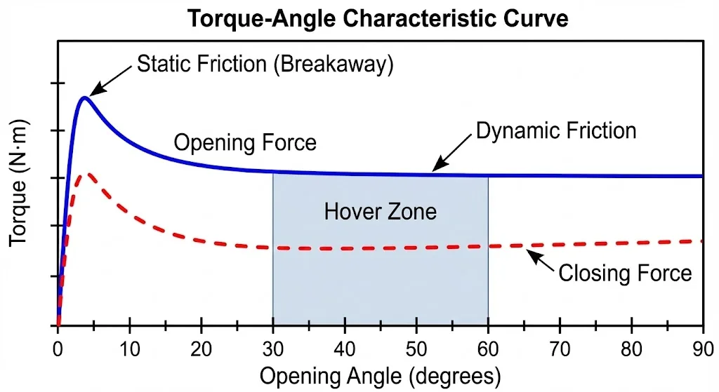
Static and Dynamic Matching
Engineering experience shows that sliding is often caused by insufficient dynamic damping leading to sudden acceleration, rather than low static torque.
Verification: Test for sliding at critical angles (e.g., 20°, 45°, 70°); check for “stiction” or sudden jumps during one-handed operation; monitor impact peaks at the close position.
Torque Retention & Variation
- Initial Torque (T0) vs. Post-Life Torque (Tn).
- Decay Rate Calculation: (T0 – Tn) / T0.
- Acceptance Goal: E.g., decay ≤20% after 100,000 cycles.
Materials and Manufacturing
- Hinge Body: Stainless steel, zinc alloy, powder metallurgy.
- Friction Components: Torque decay in friction hinges is fundamentally tied to tribological wear mechanisms and friction coefficient drift; see ASM Handbook Volume 18 for wear mechanism taxonomy and engineering control methods.
- Lubrication: Dry film or micro-lubrication (must evaluate contamination risks).
Key Focus: Torque drift under temperature; wear particles contaminating optics; corrosion/salt spray resistance.
Worked Example: Rapid Torque Estimation

Basic Estimation Formula
Applicable for cases where the center of gravity (CG) is near the geometric center. The required torque per hinge is calculated as:
T (Newton-meters) = L (meters) × W (kilograms) × 9.8 / 2
- L: Horizontal distance from the pivot to the lid’s CG (meters).
- W: Total lid weight (kilograms).
- 9.8: Acceleration due to gravity.5
- /2: Split between two hinges (adjust for single-hinge or asymmetric designs).
Calculation Case
- Lid Weight (W): 3.2 kg
- Distance to CG (L): 0.18 m
- Dual Hinges
Calculation:
T = 0.18 × 3.2 × 9.8 / 2 = 1.41 N·m (per hinge)
Critical Engineering Corrections
The basic formula is for screening only. Real-world projects must consider:
- CG Offset: ADF mechanisms and metal reinforcements often shift the CG away from the geometric center.
- Angle Dependency: CG projection changes significantly at large angles for some lids.
- Maximum Operating Force: Define the upper limit for user effort; over-specifying torque ruins the UX.
- Assembly Tolerances: Torque differences between left and right hinges can cause twisting stress and noise.
- Friction Break-in: Torque may be slightly higher initially and drop after break-in.
Best Practices
- Specify “Hovering Angles” in the Spec: Don’t just list torque in N·m. Define critical angle ranges (e.g., 20°–85°) for hovering and ensure soft-closing within the final 10° range.
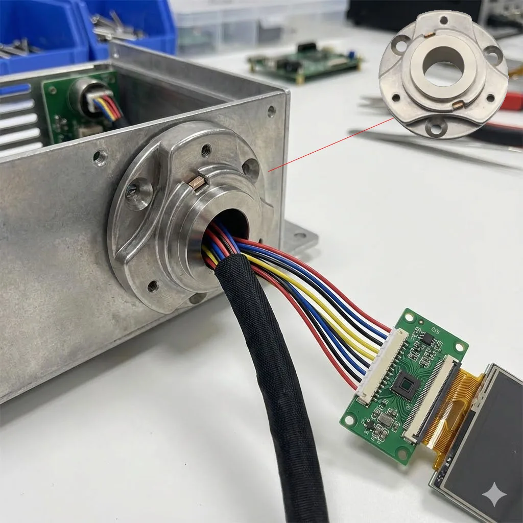
- Prioritize Hollow Hinges for Wiring: If lid contains CIS sensors, ADF sensors, or touch panels, use hollow hinges to prevent external wire bending, fatigue failure, and to reduce assembly time.
- Evaluate via Total Cost of Ownership (TCO): Torque hinges may have a higher unit cost but reduce gas spring replacements, torsion spring repairs, noise complaints, and glass breakage due to impact.
- Treat “Contamination Control” as an Optical Requirement: Evaluate powder generation, lubricant evaporation, and migration at high temperatures to protect glass and lenses.
Reliability & Compliance Standards
Environmental and Mechanical Stress
- IEC 60068 Series: Environmental testing (Temperature, humidity, vibration, shock).
- ISO 16750: Methodologies for high-stress environments.
Corrosion and Surface Treatment
- ISO 9227: Salt spray testing (Critical for transport and coastal environments).
Safety and Risk Assessment
- ISO 12100: Safety of machinery (Risk assessment for anti-slam/pinch points).
- IEC 62368-1: Safety for ICT equipment (Standard framework for safety compliance).
DVP&R (Design Verification Plan & Report) Items
- Cycle Life: 100k / 200k openings.
- Torque Retention: Post-life Tn/T0 validation.
- Temperature Cycling: -20°C to 80°C.
- Humidity/Salt Spray: Drift and corrosion checks.
- Wiring Validation: Hollow hinge wire bending life and insulation wear.
Failure Mode and Effects Analysis (FMEA Table)
| Failure Mode | Possible Cause | Effect | Prevention/Control | Detection Method |
|---|---|---|---|---|
| Rapid Torque Decay | Wear, mismatched materials, lubricant migration | Lid won’t hover, sliding risk | Wear-resistant materials; defined decay targets | Torque curve measurement; post-cycle re-test |
| Excessive Torque | Over-selection, over-tight assembly | High effort; loose screws; housing stress | Set max operating force; assembly specs | Force gauge test; assembly sampling |
| L/R Inconsistency | Batch variation, assembly deviation | Lid skewing, noise, accelerated wear | Supplier consistency control; IQC sampling | L/R torque comparison; path check |
| Noise (Squeaking) | Rough friction surfaces, particles, poor lube | User complaints; brand image drop | Material/finish specs; cleanliness control | NVH inspection; post-life sound check |
| Hinge Fracture | Insufficient strength, fatigue, drop impact | Lid detaches; safety hazard | Strength margin; impact validation; anti-loosening | FEA analysis; drop/shock testing |
| Lid Slam Impact | Low dynamic damping; poor torque curve | Glass impact; optical misalignment | Add end-of-travel damping; optimize curve | Closing speed; acceleration measurement |
| Wire Wear/Break | Insufficient bend radius, friction, poor fixing | Sensor failure; intermittent faults | Define min bend radius; protective sleeves | Wiring life test; post-cycle insulation check |
| Corrosion/Sticking | Poor plating, salt spray, humidity | Abnormal torque, sticking, short life | Plating specs; material upgrades; salt spray | ISO 9227 test; post-spray torque check |
Procurement & Design Review Checklist
Mechanical & Ergonomic Requirements
- Lid weight (W) and CG position (L) confirmed.
- Target hovering angle range defined (e.g., 20°–85°).
- Sliding threshold (angle/time) for infinite positioning defined.
- Maximum allowed operating force defined (one-handed).
- Closing impact and noise limits defined.
Torque Parameters & Consistency
- Target torque range per hinge defined.
- Total torque fluctuation goal (e.g., ±15%) defined.
- Post-life decay target (e.g., ≤20%) defined.
- Left/right consistency requirement defined.
- Supplier torque-angle curves and test methods provided.
Structure & Assembly
- Mounting method and assembly torque specs defined.
- Anti-loosening strategy (threadlocker, spring washers) evaluated.
- Space envelope verified (no interference with paper/optical paths).
Wiring & Hollow Hinges (If applicable)
- Necessity for hollow channel evaluated.
- Minimum bend radius for wire harness defined.
- Fix points, sleeves, and wear protection designed.
Reliability & Standards
- Cycle count (100k/200k) defined.
- Temperature validation range (-20°C to 80°C) included.
- Contamination check (optical area particles/evaporation) included.
Conclusion
In commercial printers and copiers, the lid mechanism is a high-frequency moving part. Its reliability and “feel” directly impact user efficiency and after-sales costs. Torque hinges provide hovering, anti-slam, a constant feel, and high lifespan within compact spaces—provided they are selected using the correct metrics, testing, and failure prevention.
FAQ
Q1: Can torque hinges completely replace gas springs?
It depends on lid weight and travel. If the goal is hovering and soft-close in limited space, torque hinges are superior. For extremely heavy lids requiring significant “lift assistance,” gas springs may still be needed, despite their temperature sensitivity.
Q2: How can I tell if the torque selection is too high?
Two indicators:
- User operating force exceeds ergonomic targets.
- Mounting points or screws show signs of loosening or stress whitening.
Always measure with a force gauge during the prototyping phase.
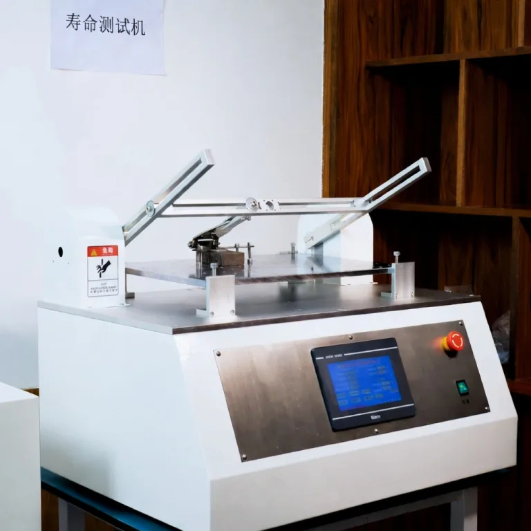
Q3: Is a cycle test alone enough for torque hinges?
No. You must also test torque retention, hovering stability, noise, assembly loosening, and contamination risks at 0, 50k, 100k, and 200k cycle intervals.
Q4: What should be noted for hollow torque hinge wiring?
Focus on the bend radius and fixing strategy. You must prevent the harness from rubbing against the hinge inner walls and check for insulation wear after the cycle test.
Q5: Are torque hinges truly insensitive to temperature?
Compared to hydraulic dampers or gas springs, friction structures are more stable. However, material and lubricant choice can still cause drift. Always perform torque re-tests after temperature cycling per IEC 60068.
Q6: How do I write torque hinge specs into a tender/RFQ?
Include the target torque range, fluctuation (±%), cycle count, decay rate, hovering requirements at specific angles, temperature validation, and acceptance test methods. Demand torque-angle curves and consistency control plans from the supplier.