Torque Hinge Calculation & Selection Guide: Formulas & Standards
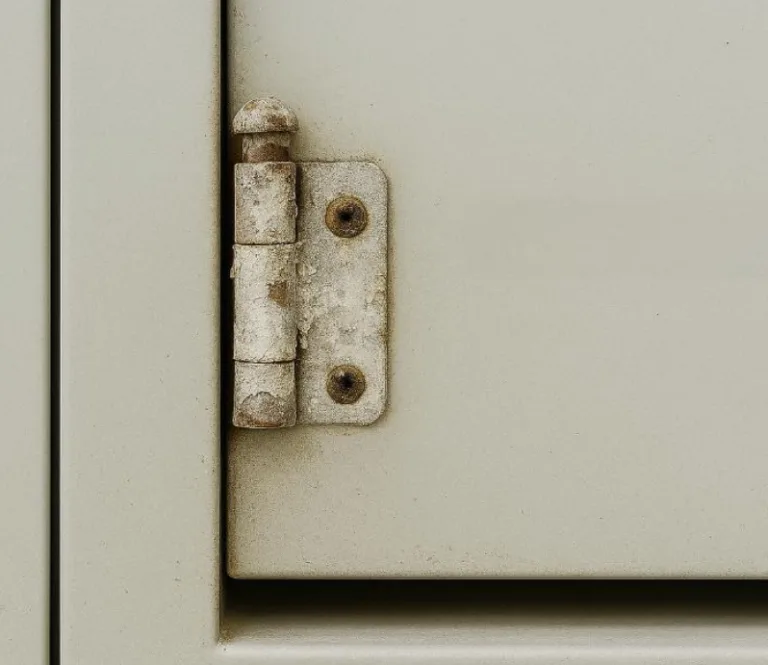
Torque hinges (also known as friction hinges or free-stop hinges) introduce controllable damping and holding torque within a rotational joint. They allow a cover, display, or door to hold its position at any angle without spring-back, ensuring a consistent feel during opening and closing.
In laptops, industrial equipment service doors, medical display arms, and precision instruments, these hinges directly affect HMI (Human-Machine Interface) quality, product lifetime, and safety.
This comprehensive guide provides practical torque calculation methods, a selection workflow, material essentials, and technical standard references to streamline your design process.
Basic Principles of Torque Hinges
Definition and Physical Meaning
Torque ($T$): The rotational force, defined as the product of the applied force and the moment arm.
- Unit: N·m (Newton-meter), per ISO 80000-4:2019 quantities and units in mechanics.
In a hinge structure, gravity generates a gravitational moment via the perpendicular distance from the panel’s center of gravity to the rotation axis. The hinge’s internal friction pair produces a resisting friction torque. The balance between the two determines whether the part holds its position.
Static Torque vs. Dynamic Torque
When selecting a hinge, it is critical to distinguish between these two concepts:
- Static Torque: The torque required to hold the panel stationary at a specific angle against gravity. Design calculations primarily focus on this value.
- Dynamic Torque: The torque required to move the panel (overcoming inertia and kinetic friction).
- Note: High-viscosity damping grease typically causes dynamic torque to be slightly higher than static torque. This prevents “bouncing” but requires slightly more force from the user to initiate movement.
Working Mechanism
Internally, stacked friction plates (e.g., steel/phosphor bronze) or preloaded elastic elements create constant or near-constant damping.
- Holding Condition: When
Friction Torque ≥ External Disturbance Torque(Gravity + Vibration), the angle is stably “locked.” - Relevant Tests:
Classification by Structural Form
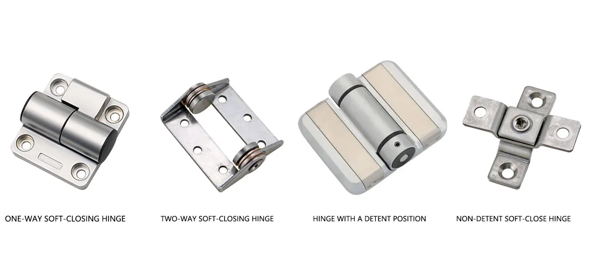
| Type | Description | Typical Application |
| Unidirectional | Provides damping mainly in one direction (e.g., damping on close, free on open). | Heavy maintenance covers, top-loading bins. |
| Bidirectional | Symmetric damping in both opening and closing directions. | Laptop screens, medical monitors, POS displays. |
| Indexed (Detent) | “Clicks” into place at set angles (e.g., 0°, 90°, 180°) for tactile feedback. | Industrial positioning, foldable equipment. |
| Non-indexed | Continuous, smooth damping over the full stroke (infinite position). | Consumer electronics, high-end appliances. |
Key Parameters for Torque Hinge Selection
Basic Quantities Needed
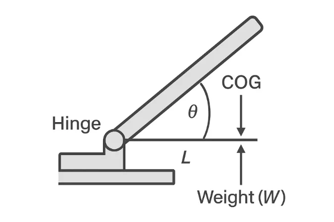
- Weight ($W$): In Newtons (N). Formula: $W = Mass (kg) \times 9.81 m/s²$.
- Moment Arm ($L$): The perpendicular distance from the Center of Gravity (COG) to the rotation axis (meters).
- Angle ($\theta$): The angle relative to the direction of gravity.
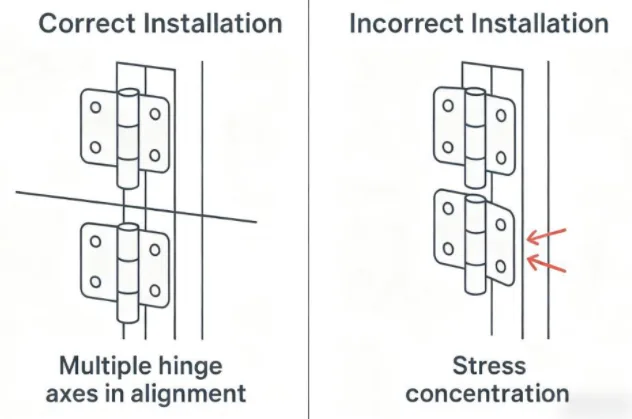
- Hinge Count ($n$): Determines the torque share per hinge.
The Torque Calculation Formula
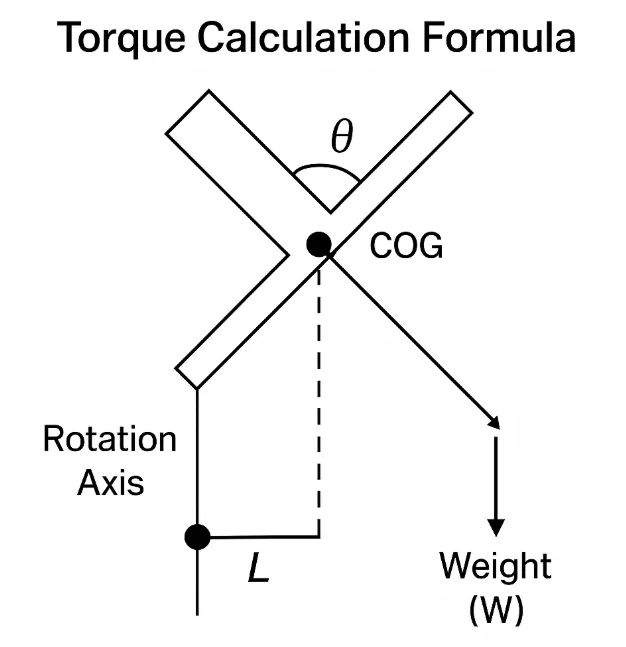
The fundamental requirement for a holding position is:
$$T_{req} = W \times L \times \sin(\theta)$$
Note: $\theta$ represents the angle where gravity has the maximum leverage. This peak almost always occurs when the panel is horizontal ($\sin 90^\circ = 1$).
Design Formula (with Safety Factor):
$$T_{design} = SF \times T_{req}$$
- Recommended Safety Factor (SF): 1.2 – 1.5 (Accounts for manufacturing tolerances, grease viscosity changes, and wear).
- T_design defines your target selection range.
Common Pitfalls
Warning:
- Mass vs. Weight: Do not use Kg directly. You must convert to Newtons ($kg \times 9.81$).
- Geometric Center vs. COG: Do not assume the geometric center is the Center of Gravity (COG). For asymmetrical panels, find the true COG in CAD.
- The Horizontal Trap: The peak torque requirement is determined when the lever arm is longest (horizontal). Always calculate for this worst-case scenario.
Calculation Examples by Application
Laptop Display (Lightweight/Precision)
- Conditions: Display mass 0.45 kg ($W \approx 4.415 N$); COG distance $L = 0.10 m$.
- Peak Condition: Horizontal (open 90° or 180° depending on layout).
- Calculation:$$T_{req} = 4.415 N \times 0.10 m = 0.4415 N\cdot m$$
- Design Target (SF = 1.3):$$T_{design} = 0.4415 \times 1.3 = 0.574 N\cdot m$$
- Selection: Two hinges sharing the load $\rightarrow$ ~0.29 N·m per hinge.
Industrial Service Cover (Heavy Duty)
- Conditions: Steel cover mass 3.0 kg ($W = 29.43 N$); COG distance $L = 0.18 m$.
- Calculation:$$T_{req} = 29.43 N \times 0.18 m = 5.30 N\cdot m$$
- Design Target (SF = 1.3):$$T_{design} = 5.30 \times 1.3 = \mathbf{6.89 N\cdot m}$$
- Selection: Two hinges $\rightarrow$ ~3.45 N·m per hinge.
- Note: For vibrating environments (generators, compressors), increase SF to 1.5 or 2.0 to prevent “creep.”
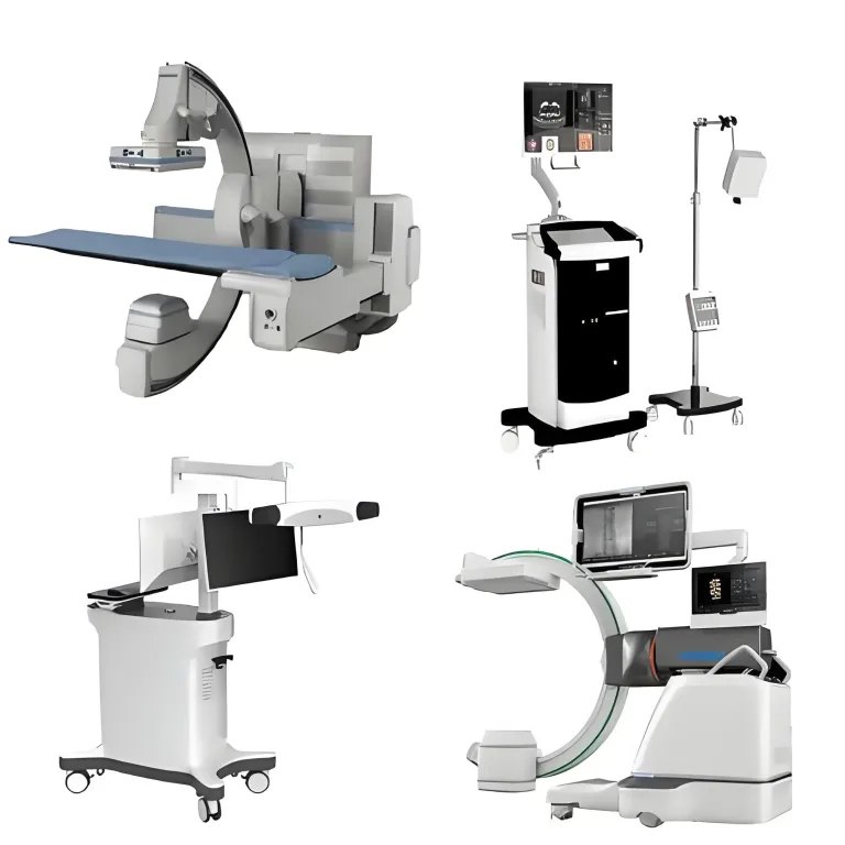
Medical Display Arm (Multi-Joint)
- Approach: Model each joint independently.
- Joint A (Base): Carries the full arm + display weight.
- Joint B (End): Carries only the display.
- Requirement: Medical environments often require specific material compatibility (cleaners) and particle emission controls (ISO Class cleanrooms).
Materials and Environmental Durability
| Material | Advantages | Risks & Notes | Related Standards |
| Stainless Steel (SUS304/316) | High strength + corrosion resistance. | Galling wear risk; higher cost. | ISO 9227 (Salt Spray); ISO 3506 (Fasteners) |
| Aluminum Alloys (6061/6063) | Lightweight, extrudable. | Low surface hardness; needs anodizing. | ISO 7599 (Anodizing); ISO 2081 (Zn plating) |
| Engineering Plastics (POM/PA+GF) | Low friction, quiet operation, low cost. | Thermal drift (torque drops in heat), creep. | UL 94 (Flammability) |
Corrosion Note: For outdoor or chemical settings, prioritize 316L stainless steel or hard anodic coatings. Verify performance via cyclic damp heat tests (IEC 60068-2-30).
Selection Workflow (Checklist)
- Define Orientation: Determine rotation range and the “Peak Angle” (where gravity acts strongest).
- Calculate Peak Torque: $T_{req} = W \times L_{COG}$.
- Apply Safety Factor: Multiply by 1.2–1.5 to get $T_{design}$.
- Determine Load Sharing: Divide by the number of hinges ($n$).
- 5. Select Model: Match torque range and curve type (Uni/Bi-directional).
- Prototype Verification: Test for “feel,” backlash, and temperature drift (-20°C to +60°C).
Troubleshooting Guide
| Issue | Potential Cause | Solution |
| Operation feels too heavy | Preload too high; Static torque $\gg$ Dynamic torque. | Choose an angle-dependent curve; add assist springs. |
| Cover sags / won’t hold | Torque selected was based on mass, not weight; SF too low. | Increase torque grade; optimize COG. |
| Feel changes with temperature | Grease viscosity change or plastic expansion. | Use low-temp-drift friction pairs; verify per IEC 60068-2-14. |
| Squeaking / Noise | Stick-slip phenomenon; debris entry. | Check surface roughness ($Ra$); improve sealing/lubrication. |
Torque Unit Conversion Table
| Unit | Conversion to N·m | Note |
| 1 kgf·cm | 0.09807 N·m | Common in Asian markets |
| 1 kgf·m | 9.80665 N·m | Old metric standard |
| 1 lbf·in | 0.11298 N·m | Common in North American aerospace/electronics |
| 1 lbf·ft | 1.3558 N·m | Common in heavy US industrial |
Typical Torque Reference Ranges
- Small Electronics (Phones/Tablets): 0.1 – 0.6 N·m
- Laptops: 0.4 – 0.8 N·m (per hinge)
- Medical/POS Displays: 1.5 – 5.0 N·m
- Industrial Cabinets: 5.0 – 15.0 N·m
- Heavy Machinery Hatches: 20.0+ N·m (Usually requires Counterbalance Hinges or Gas Struts)
FAQ
Q1: Should I use mass or weight for selection?
Always use Weight (N). If you have mass ($kg$), calculate $W = kg \times 9.81$.
Q2: Why does the peak torque usually occur at horizontal?
Because at 90° (horizontal), the lever arm of gravity relative to the hinge axis is at its maximum length, creating the highest gravitational moment.
Q3: Do two hinges share the load perfectly equally?
Not perfectly. Assembly bias and friction differences lead to unequal sharing. This is why we apply a Safety Factor of at least 20%.
Q4: How to balance “light feel” and “strong holding”?
Use an angle-dependent torque curve (where torque is higher only at holding angles) or a composite scheme (friction hinge + gas strut) to provide lift assistance.