

Weld-On Hinge Problems: Misalignment, Distortion, Cracking and Pin Binding
The door moved freely while the hinges were tack welded. After the final welds cooled, the latch side began rubbing and the door became harder to move. That pattern is a useful clue: the hinge may not be defective at all. The assembly geometry may have changed during welding.
Weld-on hinge problems are often blamed on the hinge because the symptom appears at the pivot. In a fabricated machine enclosure, cabinet or equipment door, however, the real fault can sit in the hinge axis, the welded mounting surface, the weld itself, the heat-affected material or the moving joint inside the hinge.
Cutting the hinge off immediately removes evidence. So does forcing a stiff door until the pin “wears in.” The better first step is to identify what changed between the door, hinge and frame.
Safety boundary: support heavy doors before inspecting or reworking structural hinge connections. Isolate machinery as required by the site procedure. Welding repairs, structural rework and inspection requirements should follow the approved fabrication procedure for the project rather than a generic online welding recipe.
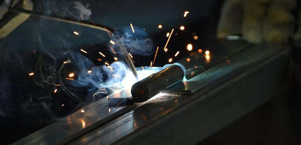
Weld-On Hinge Problems: Read the Symptom First
The timing of the symptom matters. A door that was already difficult to move before welding is a different problem from one that moved correctly during tack-up and changed only after the final weld cooled.
Use the frame, door edge and hinge pin centerlines as references. Observe before grinding, bending or loosening anything. The first table is meant to choose the diagnostic branch, not to prescribe the repair.
| Observed condition | First suspect | Evidence to inspect next |
|---|---|---|
| Door moved correctly after tack welding but binds after the final weld cooled | Weld-induced distortion or axis movement | Compare hinge centerlines, frame geometry and door gap before and after cooling |
| Door binds through most of its travel | Multi-hinge axis error | Determine whether the hinge pins still define one compatible pivot line |
| One hinge feels stiff even when it is not constrained by the complete door | Local pin, barrel, bushing or bearing problem | Inspect the moving joint for spatter, deformation, lost clearance or heat-related damage |
| Crack appears beside or through the welded joint | Weld, joint geometry, local restraint or structural loading | Record exact crack location before removing material |
| Door drops but welds and hinge axis remain stable | Door-system load path or structural sag | Inspect frame stiffness, hinge clearance and door geometry rather than assuming a weld failure |
| Surface corrosion is the main symptom | Material, weld-zone finishing or environmental exposure | Move to the material/corrosion branch rather than treating it as an alignment fault |
The key distinction is relative movement. If the hinge leaf moved on the frame, investigate the welded interface. If the whole frame moved with the hinge, the supporting structure is involved. If the leaves remain stable but the pin joint moves or locks, inspect the hinge itself.
Map the Resistance Through the Opening Arc
Do not reduce the symptom to “tight” or “loose.” Note where the resistance begins and whether it stays constant. A door that rubs only near the closed position may be contacting the frame or seal. Resistance that rises and falls through the arc is more consistent with changing geometric constraint. A hinge that remains stiff through its own motion when separated from the rest of the door points toward a local moving-joint problem.
Also record whether the door springs back when hand force is removed. Springback does not by itself prove which component is wrong, but it shows that elastic energy is being stored somewhere in the assembly. That observation is useful when separating a forced multi-hinge axis from ordinary friction at one pin.
Weld-On Hinge Misalignment
Two hinges do not merely need to be at the correct height. Their pin centerlines must form a compatible pivot system. A door can look correctly positioned when closed and still bind because the upper and lower pins are not sharing one usable axis.
This is especially easy to miss during tack-up. A few tack welds may allow enough local flexibility for the door to swing. Final welding adds heat and restraint. After the assembly cools, a small angular or lateral shift at one hinge can force the other hinge to absorb a misalignment that was not obvious earlier.
Look for several pieces of evidence together:
- one hinge appears to move freely before the second hinge is fully constrained;
- opening resistance changes noticeably through the travel;
- one hinge leaf shows witness marks or localized rubbing;
- the door springs slightly when released from a partially open angle;
- frame-to-door gaps change as the door rotates;
- pin centerlines no longer appear compatible after cooling.
Do not use the door edge alone as the alignment reference. Door panels and fabricated frames can both distort. The hinge pin system needs its own reference.
Misalignment can enter the system in more than one direction. One hinge may be shifted sideways while remaining parallel to the other, or its axis may be tilted so the two pin centerlines diverge. The door may still close under hand force in either case. What changes is the side load required to make the hinges rotate together.
That is why a static closed-door gap is not enough evidence. Compare the hinge line and door gap at several useful opening angles. If the gap and operating force change together, the assembly geometry deserves attention before the hinge is replaced.
If the problem is clearly an installation-axis issue rather than weld damage, move to the dedicated hinge-axis alignment guide for coaxiality, jigging and assembly-control details.
Heat Distortion After Final Welding
The fabrication can be dimensionally correct before final welding and wrong after it. Weld metal contracts as it cools, and the surrounding structure reacts to that shrinkage. On a thin enclosure wall, small bracket or lightly reinforced door, the hinge mounting area may move enough to change the pivot geometry.
Engineering conflict: the hinge drawing can be correct, the tack-weld position can be correct, and the door can swing smoothly during fit-up. The completed assembly can still bind after cooling because the welded structure changed shape.
That is why a post-weld check is more useful than assuming the tack condition represents the final geometry.
What to Compare After Cooling
- hinge pin centerline position relative to a fixed frame reference;
- door-to-frame gap at the hinge side and latch side;
- local flatness of the hinge mounting region;
- position of the latch relative to its keeper;
- opening resistance at several angles, not only fully closed and fully open;
- visible pulling or rotation of the welded leaf or bracket.
Do not assume a visibly flat door means the hinge geometry is stable. Local deformation around one weld may be enough to change the axis without producing a dramatic overall frame warp.
Small Movement at the Hinge Can Become a Large Door Error
The latch side is far from the hinge line, so a small angular change near a welded hinge can become much easier to see at the free edge of the door. This is one reason to measure both the local hinge mounting region and a remote door reference. A large latch-side gap change does not automatically mean the hinge itself moved by the same amount.
Make the comparison after the assembly has cooled to the intended inspection condition. Measurements taken while the local structure is still thermally expanding can describe a temporary state rather than the geometry the door will have in service.
Cracks at the Weld and Heat-Affected Zone
A crack near a weld-on hinge is not a diagnosis by itself. Before grinding the crack away, record where it begins, where it travels and whether it passes through weld metal, the weld toe, the heat-affected region or the surrounding base material.
Location changes the investigation.
| Observed crack location | What it should trigger | Evidence needed before rework |
|---|---|---|
| Through weld metal | Review weld quality, joint loading and the approved welding procedure | Crack length, weld profile, service load and fabrication record where available |
| At the weld toe | Investigate local stress concentration, weld profile and cyclic loading | Crack origin, door load path and nearby deformation |
| Adjacent to the weld in the heat-affected region | Review material behavior, restraint, heat input and local joint design | Base material, fabrication condition and exact crack path |
| Through thin sheet or bracket beside an intact weld | Investigate the supporting structure rather than assuming the weld is weak | Sheet/bracket thickness, reinforcement and door load path |
| Crack returns after a previous repair | Re-open the root-cause investigation | Determine whether distortion, loading or structural compliance remained after the first repair |
“Make the weld larger” is not a universal corrective action. A larger weld changes heat input, stiffness and local restraint. If the supporting sheet is the weak part, increasing weld size does not automatically solve the structural problem.
Repeated Cracking Is a System Warning
When a crack returns in the same region after rework, treat that recurrence as evidence that the original load path or geometry may still be wrong. The repair may have restored the surface without removing the cause.
Direction matters as well as location. A crack that follows the edge of a stiff bracket, begins at a weld termination, or appears in thin sheet beside an intact hinge can point the investigation toward different local stress paths. Photograph the area with enough surrounding structure to show the door, bracket and frame relationship; a close-up of the crack alone can remove the context needed to understand how the joint is loaded.
If the crack appeared only after a change in door mass, stop position, operating frequency or attached equipment, record that change. It may be more useful than the nominal hinge model when explaining why a previously stable joint began to fail.
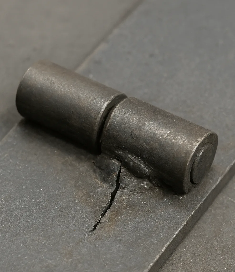
Pin Binding After Welding
A stiff hinge after welding can come from the moving joint itself or from the completed assembly forcing several hinges to rotate around incompatible axes. These two conditions feel similar at the door handle but require different corrective actions.
Local Hinge Binding
If one hinge remains stiff when it is no longer being forced by the complete door geometry, inspect the local hinge joint. Relevant evidence can include weld spatter near the moving interface, barrel distortion, reduced running clearance, damage to a bushing or bearing, or heat transferred into a hinge design that contains temperature-sensitive internal components.
Lubricant may reduce ordinary friction. It cannot restore lost geometry or repair a damaged bearing surface.
Assembly-Induced Binding
If each hinge can rotate acceptably when unconstrained but the complete door becomes stiff when both or all hinges are connected, inspect the common-axis relationship before blaming the pin.
The assembly may be forcing one hinge sideways or angularly because the pin centerlines do not agree. This condition often changes resistance through the opening arc rather than producing one constant amount of friction.
When the equipment design allows safe isolation, support the door so its weight is not using one hinge as a pry bar during diagnosis. The objective is to determine whether the resistance stays with one hinge or appears only when the hinges are required to work together. Do not perform this isolation by partially cutting structural welds on an unsupported door.
Watch the barrel and leaves while the door is moved slowly. A local hinge problem tends to remain concentrated at the same joint. Assembly-induced binding often shows a different pattern: one hinge or its mounting region deflects as the door approaches the angle where resistance rises.
When the Weld Is Not the Root Cause
Not every problem beside a welded hinge is a welding problem.
If the hinge axis is stable and the welded mounting areas remain intact, a dropped latch-side corner may come from hinge clearance, frame deformation or the overall door load path. Use the industrial door hinge sag diagnosis instead of repeatedly rewelding a stable joint.
If the question is whether a welded or bolted architecture is more appropriate for the project, that is a selection problem rather than a failure diagnosis. Use the weld-on vs bolt-on hinge guide.
Corrosion boundary: rust or staining around a weld zone can affect hinge performance, but stainless grade selection, coatings, galvanic compatibility and environmental exposure are separate material decisions. If corrosion is the primary symptom, do not turn an alignment or cracking diagnosis into a general corrosion-selection article.
When Corrosion Is the Main Symptom
A stainless weld-on hinge can be the right material choice for a corrosive environment and still require attention at the completed joint. The hinge material name does not, by itself, describe the condition of the weld zone, adjacent base metal, surface restoration, trapped moisture or contact with dissimilar materials.
For this page, corrosion becomes relevant when it explains the observed failure: rust products interfere with motion, section loss appears near a loaded joint, or corrosion obscures a crack or mounting defect. If the project question is instead “Which material or finish should we specify for the environment?”, move that decision to the material/corrosion article rather than expanding this failure diagnosis into a second selection guide.
For an OEM project where the real question is what information should be defined on the drawing, welding specification or supplier package, use the weld-on industrial hinges OEM guide.
Match the Repair to the Evidence
The corrective action should remove the condition that produced the symptom. Grinding or cutting first can erase the evidence needed to make that decision.
| Evidence found | Corrective direction | Do not assume |
|---|---|---|
| Hinge axis moved after final welding | Restore the required geometry using the approved fabrication/rework method and verify again after cooling | Forcing the door through several cycles will self-align the hinges |
| Local frame or bracket pulled during welding | Correct the structural distortion and then re-establish hinge geometry | A stronger hinge will straighten the mounting structure |
| Crack exists in weld, weld toe, HAZ or adjacent base material | Support the door, preserve the crack evidence and review the joint/load path before repair | A larger replacement weld is automatically safer |
| One hinge binds locally when unconstrained | Inspect the hinge joint and replace or rework the affected component as appropriate to its design | Lubrication cures deformation or damaged internal components |
| Individual hinges move freely but the assembled door binds | Restore compatible hinge axes and mounting geometry | The pin itself is the primary failure |
| Welds and axes remain stable but the door drops | Move to structural door-sag diagnosis | The visible proximity of the weld proves the weld caused the failure |
For critical equipment, the actual repair method may require an engineering review or approved welding/rework procedure. The diagnosis on this page identifies the branch; it does not replace project-specific fabrication requirements.
Verify the Door After Rework
Do not accept a repair while the structure is still hot or while the door is being artificially supported in a position that hides the original symptom. Let the relevant assembly return to its intended inspection condition, then repeat the same references used before rework.
- compare hinge pin centerlines or the defined alignment reference;
- inspect the welded area and adjacent base material;
- compare door-to-frame gaps with the approved geometry;
- operate the door through its required travel and note any changing resistance;
- confirm the latch engages without lifting, pushing or forcing the door;
- confirm there is no new interference between hinge leaves, barrel, frame or door panel;
- record the repaired baseline if the application requires later comparison.
A repair is successful when the original weld-on hinge problem is no longer present because the actual cause was corrected—not merely because the door can be forced through one opening cycle. The final record should show what changed, what evidence identified the cause, what was reworked, and whether the cooled assembly now maintains the required hinge motion and door geometry.
Questions That Change the Diagnosis
Why does a weld-on hinge bind after welding?
Binding after welding can result from weld-induced distortion, incompatible hinge axes, local barrel or pin deformation, weld spatter near the moving joint, or damage to an internal bushing or bearing. If the door moved correctly during tack-up and became stiff only after final welding cooled, inspect geometry and distortion before assuming the hinge pin itself failed.
Can a misaligned weld-on hinge be corrected without cutting it off?
It depends on the amount and type of misalignment, the joint design, surrounding structure and the approved rework procedure. Minor geometric errors and severe post-weld distortion should not automatically be treated the same way. Record the current axis and frame condition before removing weld material or repositioning the hinge.
Why can a crack appear beside the hinge weld instead of through the weld?
The surrounding sheet, bracket, weld toe or heat-affected region may be carrying high local stress even when the visible weld remains intact. Crack location should be recorded before grinding because it helps determine whether the investigation should focus on weld quality, local restraint, structural stiffness or the door load path.
Can welding heat damage a hinge pin, bushing or bearing?
It can in some hinge designs, depending on the materials, internal construction, heat path and welding procedure. Do not assume every stiff hinge has heat damage. Separate local hinge binding from assembly-induced axis binding before deciding that the internal hinge components were affected.
How can I tell weld distortion from an overloaded door hinge?
Weld distortion usually leaves evidence that the hinge or nearby structure changed position during fabrication or cooling. An overloaded or structurally undersized door system may sag even when the welds and hinge axes remain stable. Compare the post-weld geometry first; if the welded structure is stable but the door still drops, move to a structural door-sag diagnosis.
Share Weld Photos and Door Symptoms
If a welded industrial door starts binding, shifting or cracking, send clear photos of each hinge and weld zone, the complete door and frame, the symptom location, and a short description of when the problem appeared—during tack-up, after final welding, after cooling or after service.
Those details provide a better starting point for separating axis movement, weld distortion, cracking, local hinge binding and a non-weld structural problem.
Send Failure Details

 English
  한국어
한국어  Русский
  Español
  Italiano
  Deutsch
  Français
  Português