Torque Hinge Design for 5mm Ultra-thin Devices: 30°–150° Screen Free-stop
Achieving 30° to 150° screen free-stop within a 5mm total device thickness is one of the most demanding structural requirements in ultra-thin consumer electronics and precision medical devices. The hinge must deliver stable resistance torque in a tightly constrained space so the screen can hold position across multiple angles without drifting, while still meeting durability, environmental reliability, and assembly consistency targets.
This guide explains how to design and select a torque hinge (constant friction hinge) for ultra-thin free-stop applications. You’ll learn core definitions, typical benchmarks, torque calculation methods, worked examples, selection workflow, reliability tests, failure modes, and industry-specific best practices.
What Is Screen Free-stop, and Why Is It Hard at 5mm Thickness?
What “Free-stop” Means (30°–150° Holding Range)

A screen “free-stop” design means the display can stay at any angle in a range (here: 30°–150°) without spring-back or falling due to gravity. It is also called:
- Stepless stop
- Free-position hinge
- Constant torque holding
In practice, the hinge must provide enough resistance torque to counteract the screen’s gravity torque at every usable angle.
Why 5mm Total Thickness Creates a High-Difficulty Constraint
With only 5mm available, hinge designers face three constraints simultaneously:
- Limited hinge diameter
- Limited fixation structure thickness (thin walls deform easily)
- Limited routing space for FPC and cable movement
This is why many alternatives (springs, ratchets, magnetic stops) often struggle in this thickness range.
Key Technical Requirements for Free-stop in 5mm Ultra-thin Devices
Spatial and Structural Constraints (Typical Values)
The values below are typical design references. Actual numbers must be validated via tolerance stack-up and structural analysis:
- Housing thickness: typically 0.8mm–1.2mm per side
- Effective hinge diameter range: typically 2.6mm–3.4mm (including supports and clearances)
- Fixation strength requirement: hinge base must resist torsion and prevent local deformation
Free-stop Angle Ranges (Engineering Interpretation)
- Effective free-stop range: 30°–150°
- 0°–20° range: often designed for auto-close or light damping
- Above 150° region: often limited by interference, FPC bending radius, or housing stiffness
Reference Standards (Recommended Use Cases)
- Safety and mechanical strength: IEC 62368-1 (Official standard page)
- Environmental reliability: EN 60068 series
- Corrosion and salt spray: ASTM B117
Key Definitions You Must Clarify Before Selecting a Torque Hinge
This section prevents common misunderstandings during torque hinge selection.
Holding Torque vs. Breakaway Torque
- Holding torque: the torque required to keep the screen from moving at a given angle
- Breakaway torque: the initial torque required to start rotation from rest (often higher than running torque)
Static vs. Dynamic Friction (Why Jitter Happens)
- Static friction controls how the hinge behaves when the screen is stationary
- Dynamic friction affects how smooth the hinge feels during movement
A large static–dynamic gap often causes:
- Startup shaking
- Uneven movement feel
- Angle jumping at small rotations
Torque Curve Consistency
Even if the average torque is correct, poor torque curve consistency can cause free-stop failure at certain angles.
Typical engineering target:
- Torque tolerance: within plus/minus 10 percent of rated value
Benchmarks: Typical Metrics for Ultra-thin Torque Hinge Design
This section helps teams set measurable acceptance criteria early.
Typical Design Benchmarks
- Torque tolerance: plus/minus 10 percent (tighter control improves consistency but increases cost)
- Torque decay after life test: less than or equal to 15 percent (depends on material, coating, and lubricant)
- Life cycles: 20,000 to 50,000 cycles (consumer and industrial vary)
- Temperature range target: minus 20 degrees C to 60 degrees C (extend for automotive or extreme use)
Why Benchmarks Matter
They help you:
- Set measurable acceptance criteria
- Avoid selecting hinges based only on initial feel
- Prevent late-stage redesign due to torque decay or noise
Why Torque Hinges Work in 5mm Ultra-thin Free-stop Designs
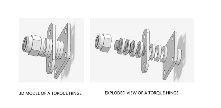
A torque hinge generates resistance torque via controlled friction, providing predictable damping in small sizes.
Mechanism of Constant Resistance Torque
A torque hinge typically consists of:
- Shaft
- Friction clips or friction rings
- Fixation structure
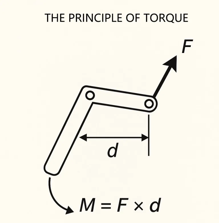
A simplified torque relationship is:
Torque (T) is approximately equal to friction coefficient (mu) multiplied by normal pressure (N) multiplied by effective friction radius (r).
T ≈ mu × N × r
Where:
- T = hinge resistance torque (N·m or N·mm)
- mu = friction coefficient
- N = normal pressure
- r = effective friction radius
Material Selection (Typical Engineering Choices)
- Shaft material: AISI 420 stainless steel (property reference: MatWeb data sheet)
- Friction clip material: SK5 (JIS carbon tool steel grade; reference: JIS G 4401)
- Key design goal: torque stability and wear resistance, not peak torque
Torque Calculation: How to Calculate Required Hinge Torque
Total Required Torque for Free-stop
The hinge torque must exceed the gravity torque of the screen.
A typical calculation model is:
Treq ≥ W × L × sin(theta) × SF
Where:
- Treq = required total resistance torque
- W = screen weight in Newtons (W = m × g)
- L = distance from screen center of gravity to hinge axis (meters)
- theta = angle relative to gravity direction
- SF = safety factor (typical 1.2 to 1.5)
Notes:
- The sine function is used in many simplified models, but in real designs the correct term depends on how you define theta and hinge axis direction.
- If your geometry is unclear, calculate both 30 degrees and 150 degrees as worst-case candidates and validate with prototype testing.
Dual Hinge Distribution
For left and right hinge products:
Thinge ≥ (Treq ÷ 2) × K
Where:
- Thinge = target torque for a single hinge
- K = distribution coefficient (recommended 1.05 to 1.15) to account for assembly deviation and friction unevenness
Worked Examples (Practical Calculations)
Worked examples help teams apply the method quickly.
Example A: Ultra-thin Consumer Device (Light Screen, Wide CG Offset)
Assumptions:
- Screen mass m = 120g = 0.12kg
- CG offset L = 55mm = 0.055m
- Angle theta = 150 degrees
- Safety factor SF = 1.3
- Dual hinge coefficient K = 1.1
Step 1: Calculate weight W
W = m × g
W = 0.12 × 9.81 = 1.177 N
Step 2: Calculate total required torque Treq
Treq ≥ W × L × sin(theta) × SF
sin(150 degrees) = 0.5
Treq ≥ 1.177 × 0.055 × 0.5 × 1.3
Treq ≥ 0.0421 N·m
Convert to N·mm:
0.0421 N·m = 42.1 N·mm
Step 3: Calculate target torque per hinge Thinge
Thinge ≥ (Treq ÷ 2) × K
Thinge ≥ (42.1 ÷ 2) × 1.1
Thinge ≥ 23.2 N·mm
Recommendation:
Select a torque hinge around 23 N·mm per side, with torque tolerance plus/minus 10 percent and torque decay less than or equal to 15 percent after life testing.
Example B: Precision Medical Device (Higher Cleanliness, Higher Reliability)
Assumptions:
- Screen mass m = 200g = 0.2kg
- CG offset L = 65mm = 0.065m
- Angle theta = 30 degrees
- Safety factor SF = 1.5
- Dual hinge coefficient K = 1.1
Step 1: Calculate weight W
W = 0.2 × 9.81 = 1.962 N
Step 2: Calculate total required torque Treq
Treq ≥ 1.962 × 0.065 × sin(30 degrees) × 1.5
sin(30 degrees) = 0.5
Treq ≥ 1.962 × 0.065 × 0.5 × 1.5
Treq ≥ 0.0957 N·m
Convert to N·mm:
0.0957 N·m = 95.7 N·mm
Step 3: Calculate target torque per hinge Thinge
Thinge ≥ (95.7 ÷ 2) × 1.1
Thinge ≥ 52.6 N·mm
Recommendation:
Design for approximately 53 N·mm per hinge and set stricter standards for noise, debris control, and environmental validation.
Selection Workflow (Mass Production Oriented)
- Collect screen mass and CG location
- Identify worst-case angles and calculate Treq
- Define torque tolerance and torque decay thresholds
- Select hinge structure: single shaft, segmented, or multi-clip
- Define coating and lubrication strategy
- Build reliability test plan and acceptance criteria
- Validate assembly variation via tolerance stack-up analysis
Good Methods vs Bad Methods (Practical Guidance)
Good Methods (Recommended)
- Use torque calculation and verify with physical torque testing
- Validate torque curve consistency across angles
- Run life cycle plus temperature plus vibration tests
- Measure torque decay, noise, and debris generation
- Use surface treatment and controlled lubrication to reduce friction gap
Bad Methods (Avoid)
- Selecting hinges only by initial feel
- Ignoring torque decay after life testing
- Ignoring static to dynamic friction gap
- Skipping tolerance stack-up analysis
- Skipping dust contamination risk for medical designs
Manufacturing and Friction Control for 5mm Structures
MIM (Metal Injection Molding)
- Suitable for complex hinge seats and brackets
- High consistency and reduced machining
- Verify strength and fatigue performance for load-bearing parts
DLC Coating and Lubrication
- DLC improves wear resistance
- Use low-volatility grease to prevent migration
- Reduce debris generation and torque fluctuation
Industry-Specific Best Practices
Consumer Electronics
- Prioritize torque consistency, cost, and low noise
- Use segmented hinge modules for improved stress distribution
- Ensure FPC routing reliability and bending margin
Precision Medical Devices

- Prioritize cleanliness, low debris, and long-term stability
- Add sealing rings or encapsulated hinge modules
- Use stricter torque decay and noise thresholds
- Validate sterilization-related risks if applicable
Automotive Displays

- Validate wider temperature ranges and vibration conditions
- Improve fixation rigidity and anti-loose design
- Pay special attention to noise and torque shift at low temperatures
Reliability Testing and Acceptance Metrics
- Life cycles: 20,000 to 50,000
- Torque decay: less than or equal to 15 percent
- Salt spray: ASTM B117, 48h or 96h
- Temperature: minus 20 degrees C to 60 degrees C or wider
- Vibration and shock: fixation integrity and FPC protection
Failure Modes and Countermeasures
| Failure Mode | Cause | Impact | Countermeasure |
|---|---|---|---|
| Torque decay | wear, grease migration | screen drifts | coating + grease control |
| Startup jitter | static/dynamic gap | poor feel | surface treatment optimization |
| Noise | dry friction, debris | UX and reliability risk | sealing + stable lubrication |
| Dust pollution | metal wear particles | contamination | sealing rings, low-wear materials |
| Loose base | weak fixation | misalignment | reinforced seat + anti-loose design |
Checklist (Quick Reference)
Before selecting a torque hinge for 5mm free-stop designs, confirm:
- Screen mass and CG offset verified
- Worst-case angle identified
- Target torque per hinge calculated
- Torque tolerance defined (plus/minus 10 percent typical)
- Torque decay threshold defined (less than or equal to 15 percent typical)
- FPC routing path validated
- Fixation structure stiffness validated
- Life and environmental tests planned
Tools and Resources
Measurement tools:
- Torque gauge or torque tester
- Surface roughness measurement tools
- Micro hardness testing
- Debris inspection microscope
Reliability tools:
- Cycle test jig
- Temperature chamber
- Vibration test system
Simulation:
- FEA tools are recommended for fixation strength and deformation validation. For engineering simulation best practices and validation guidance, refer to NAFEMS (official).
FAQ
Will dust from long-term friction affect electronics?
Yes. Use sealing structures, low-wear materials, and stable lubrication. Medical devices should adopt stricter contamination control designs.
Does a 5mm chassis withstand stress at 150 degrees?
Yes if the hinge fixation zone is reinforced. Thin-wall deformation is a common failure cause, so local reinforcement is required.
Will temperature changes affect free-stop performance?
Yes. Lubricant viscosity and thermal expansion can shift torque. Validate using EN 60068 methods and reserve torque margin.
How do I decide worst-case angle for torque calculation?
Use the angle where gravity torque is maximized based on hinge axis and center-of-gravity geometry. Evaluate both 30 degrees and 150 degrees if uncertain.
Why does the hinge feel smooth initially but fail after cycles?
Torque decay may occur due to wear and lubricant migration. Acceptance criteria must include life testing and post-test torque verification.
Can magnetic stops replace torque hinges in 5mm designs?
Magnetic systems usually require additional thickness and mechanical limit structures. They may work in hybrid designs but often cannot replace torque hinges alone in 5mm designs.