

How to Measure an Industrial Butt Hinge for Replacement
A replacement inquiry often arrives with one photograph, the hinge height, and a note that says “same as this.” That may be enough to recognize a general hinge family. It is not enough to reproduce the way the old hinge places the door.
To measure an industrial butt hinge for replacement, record the installed orientation before removal, then measure the leaf geometry, hole pattern, pin and knuckle, closed thickness, and pivot location from consistent references. Wear must be identified separately. A used pin, an oval bore, or an elongated mounting hole can describe the failure, not the original size.
Replacement work begins with an existing assembly whose fit, motion, and service history can still be observed. A new-door project needs a different starting point: the broader industrial butt hinge selection guide covers hinge architecture and initial selection.
Working rule: Preserve the installed relationship first. Measure the loose part second. A bench measurement cannot recover a door gap, hinge orientation, shim stack, or loaded-side wear pattern that was never recorded.
The Used Hinge Is Evidence, Not a Master
A service part contains three kinds of information. Some features still represent the manufactured geometry. Some have been changed by wear, corrosion, coating buildup, fastener movement, or impact. Others only make sense in relation to the door and frame.
This distinction matters because reverse measurement can produce a precise record of the wrong condition. A caliper can accurately report the smallest diameter across a worn flat on the pin. Ordering that value as the replacement diameter would build the wear loss into the new part. The same error occurs when an elongated mounting hole is treated as the released hole size or a bent leaf is forced flat before its installed offset is documented.
Keep three columns in the measurement record: observed condition, likely nominal feature, and replacement requirement. They are not automatically identical. The observed condition comes from the used hinge. The likely nominal feature needs an unworn surface, a retained sample, an original drawing, or a comparison across several parts. The replacement requirement also has to preserve the installed function.
The outside shape can match. The pivot can still land in the wrong place.
At HTAN, a typical replacement inquiry starts with one product photo, one overall height, and a request for “the same hinge.” That information can narrow the hinge family, but it cannot release a replacement. We next ask for the installed side view, open and closed views, hole locations tied to the pivot, and any shims or washers. Those details often show that an apparent match would move the door even when the leaf outline and basic hole pitch look right.
Before the Fasteners Move
Start with the door supported and the hinge still carrying its normal relationship to the frame. The purpose is not to diagnose every fault. It is to retain information that disappears as soon as the fasteners, shims, washers, or pin are removed.
- Photograph the complete door and frame, then photograph each hinge station from the front, side, top, and pin end.
- Label the hinge station, such as upper, middle, or lower. Do not mix pins, washers, shims, or leaves from different positions.
- Mark the top of the hinge, the frame leaf, the door leaf, and the loaded side. Add a clocking mark across the pin and knuckle if the pin may rotate during removal.
- Record whether the pin head, clip, groove, peened end, thread, or other retainer is at the top or bottom.
- Measure the closed door gap at several heights and note any shim or spacer beneath each leaf.
- Record the opening direction, required opening angle, and the nearest frame return, gasket, trim, latch, or obstruction.
- Mark the installed fastener position inside every slot before loosening the joint. The slot center is not necessarily the assembled position.
- Note whether the door changes position as individual fasteners are released. That movement shows that the installed parts were carrying preload or compensating for distortion.
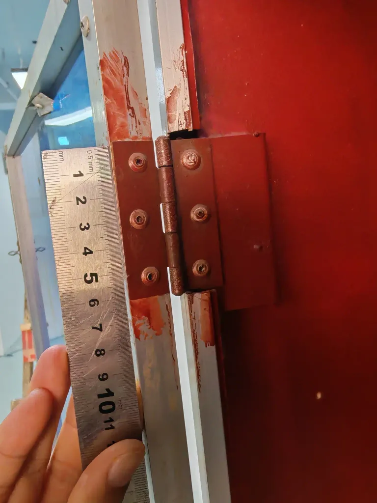
Do not clean the hinge before the first photographs. Rust tracks, fretting marks, paint witness lines, compressed sealant, and polished contact bands can show how the part sat in the assembly. After those observations are recorded, clean only the surfaces needed for measurement and keep the original orientation marks visible.
Choose References Before Dimensions
Hole-to-hole measurements are easy to collect and difficult to use when several tolerances have accumulated. A replacement record becomes more useful when each feature is located from the same functional references.
| Measurement Reference | Practical Definition | What It Locates |
|---|---|---|
| Pivot reference A | The pin centerline, or a clearly stated method used to estimate it | Leaf reach, hole offset, door stand-off, and swing geometry |
| Mounting reference B | A stable, flat mounting surface on the frame or door leaf | Closed thickness, steps, offsets, and leaf flatness |
| End reference C | One undamaged end face or a marked transverse line | Hole rows, knuckle segments, slots, and overall height |
The pin centerline is not always directly accessible. A pin end may be recessed, headed, peened, or covered. The center can sometimes be inferred from an exposed pin diameter or a concentric barrel outside diameter, but the method must be stated. A rolled knuckle is not guaranteed to be perfectly round or concentric with the working bore, especially after service.
For each mounting hole, record an X location from the pivot reference and a Y location from the selected end. This coordinate method avoids a chain of neighboring hole pitches. It also makes an offset pattern, unequal leaves, or a shifted slot immediately visible.
Overall Size with the Leaves Open
Remove paint flakes, loose debris, and raised burrs only where they prevent the measuring faces from seating. Then place the hinge in its natural open condition. Do not assume every industrial butt hinge is designed to lie perfectly flat at 180 degrees. Formed leaves, offset leaves, stops, weld lands, and reinforced sections can establish another open relationship.
Record the following base dimensions:
- Overall height: maximum length parallel to the pin axis, excluding a removable pin projection unless that projection controls clearance.
- Open width: maximum distance across both leaves in the defined open condition.
- Individual leaf width: pivot reference to each outer edge. Measure the frame leaf and door leaf separately.
- Leaf thickness: base material plus any finish at the measurement point. Avoid a countersink, embossed rib, rolled edge, weld bead, or deformed corner.
- Corner and edge form: square, radiused, chamfered, folded, cranked, or locally relieved.
- Natural open angle: the leaf relationship without forcing a bent or stopped hinge flat.
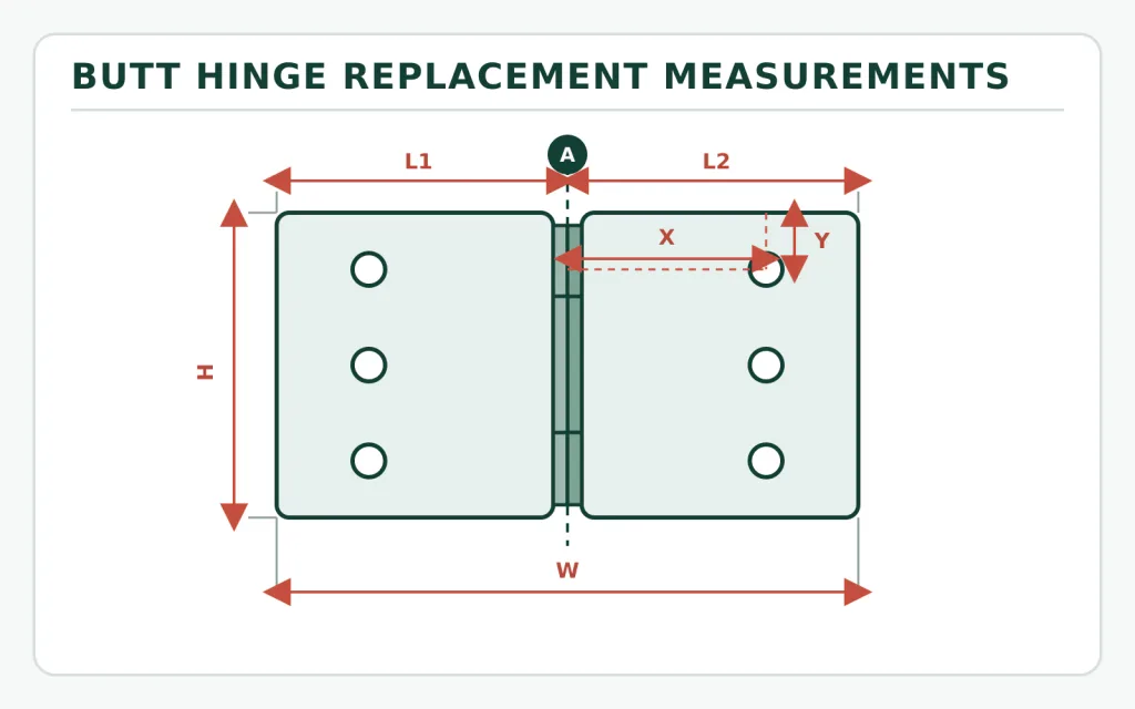
Take more than one thickness reading. A stamped leaf may show edge rollover, coating buildup, local dish around a hole, or permanent bending from the mounting joint. Report the measurement location rather than presenting one value as though the entire leaf were uniform.
Hole Pattern from Functional References
A replacement can share the same overall height and open width yet miss every hole. More subtly, all fasteners may enter while the new pin axis sits closer to or farther from the door edge. That changes the door gap and sweep even though the bolt pattern appears usable.
Draw a simple view of each leaf. Number the holes, identify the pivot and end references, and record the center coordinates. For a symmetric pattern, measure it rather than assuming symmetry. For an offset pattern, identify which leaf belongs to the frame.
Round holes, slots, and formed seats
- Round clearance hole: record diameter and inspect for ovality or fastener witness marks.
- Slot: record overall length, width, end radius, orientation, and centerline. Also retain the marked installed fastener position.
- Countersink: record the leaf side, major diameter, included-angle requirement if known, and mating screw-head style.
- Counterbore or spotface: record recess diameter, depth, and the surface from which depth was measured.
- Extruded or tapped hole: record thread or extrusion direction, usable engagement, and whether the feature is in the hinge or receiving structure.
A countersunk screw can pull a leaf sideways if the replacement countersink is misplaced or does not match the head. A slot can hide the mismatch during assembly, then allow the hinge to move when clamp load is inadequate. The replacement drawing therefore needs the hole form and its location, not only a center-to-center pitch.
When the purchasing decision depends mainly on spacing tolerance, hole type, or drawing communication, continue with the dedicated hinge mounting-hole pattern guide. Here, the pattern is recorded only as one part of the complete replacement geometry.
The Mating Structure Is Half the Pattern
The old leaf can hide the condition of the door and frame beneath it. After removal, photograph and measure the receiving structure before filling, drilling, grinding, or installing an adapter plate. Record panel thickness, backing plates, threaded inserts, weld studs, captive nuts, through-bolt access, and the distance from the receiving holes to the same door or frame references used for the hinge.
Look for elongated panel holes, pulled inserts, cracked paint, local dish, raised welds, sealant beds, and permanent witness marks. A round hole in the hinge leaf does not prove the receiving hole remained round. A slot in the leaf may have allowed the hinge to be assembled away from its geometric center. If that installed position was not marked, measuring the loose leaf alone cannot reconstruct it.
Also record the actual fastener system: head style, shank or thread size, washer arrangement, grip length, nut or insert type, and available tool clearance. These details determine whether a candidate countersink seats correctly and whether the joint can be tightened without changing the hinge position.
State whether the requirement is a drop-in replacement or an adapted replacement. A drop-in part must work with the existing holes, axis location, mounting faces, and service access. An adapted replacement may use a new hole pattern or reinforcement, but that is a controlled modification to the assembly, not proof that the hinges are dimensionally interchangeable.
Pin and Knuckle Geometry
The visible barrel is a stack of working features. Record the total barrel length, knuckle outside diameter, number and order of knuckle segments, individual segment lengths, gaps between segments, pin projection, and the details at both pin ends.
If the pin is designed for removal and the door is safely supported, label every washer, spacer, and bushing as it comes off. Measure the pin at several axial stations and at more than one rotational direction. A micrometer is better than a caliper for detecting a small worn flat, but neither reading should be declared nominal until an unworn area or other reference supports it.
For each knuckle, distinguish the outside diameter from the working bore. A caliper across the barrel does not establish the bore size. An accessible bore can be checked in more than one direction and at both ends to look for ovality or bellmouth wear. A plug or pin gage can screen size, but a gage that enters does not by itself prove the complete bore is straight or coaxial.
Do not drive out a peened, staked, welded, or otherwise nonserviceable pin merely to complete a measurement sheet. Record the retention construction and ask whether the candidate replacement must provide the same service behavior. A removable pin and a permanently retained pin may share the same nominal diameter while creating very different maintenance and safety conditions.
Closed Thickness and Pivot Offset
Open dimensions help identify the loose hinge. Closed geometry determines where the door sits. Bring the leaves together in the same relationship used in the assembly and record the total closed thickness, any designed leaf gap, steps between mounting faces, and the distance from the pivot centerline to each mounting face.
Measure the frame side and door side separately. An offset hinge may place the pivot near one mounting face and far from the other. A cranked leaf may move the door around a return flange. A spacer may be an intentional part of that geometry rather than an installation correction.
This is where a visually convincing substitute often fails. Its leaves cover the old marks and its screws enter the existing holes, but the pin centerline moves. The latch no longer aligns, the gasket compression changes, or the door edge strikes the frame before reaching the required angle.
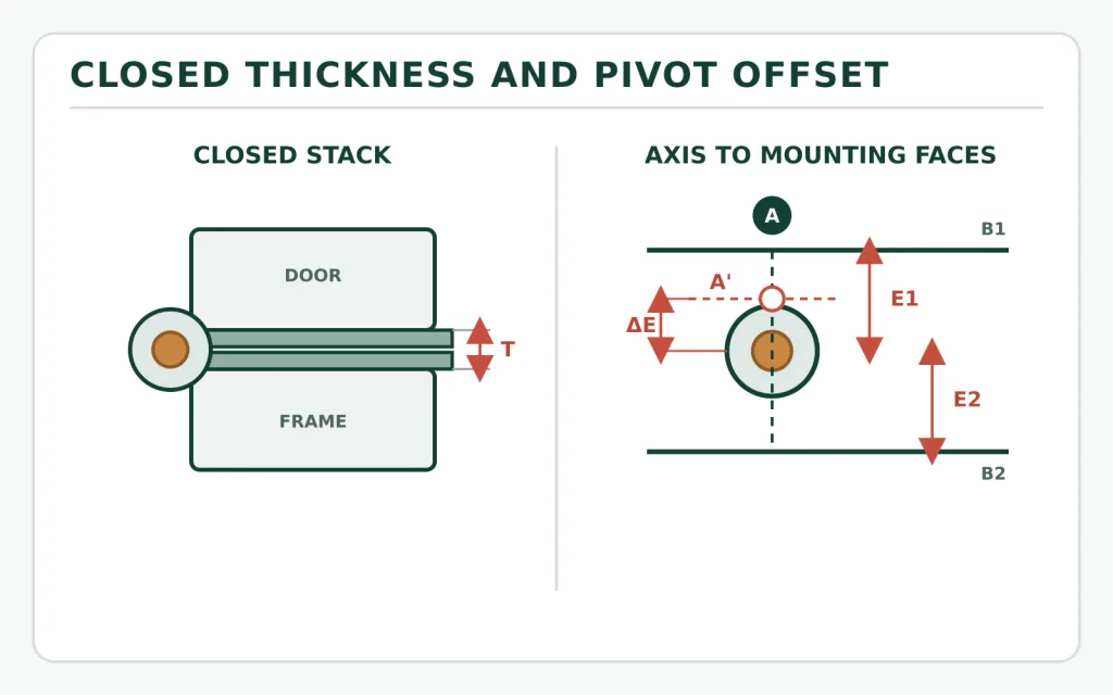
Bench-fit conflict: Matching open width and mounting-hole pitch can still move the installed axis. Include at least one closed side view with the axis-to-mounting-face relationship. Without it, a supplier can match the plate and miss the door position.
Wear Changes the Number
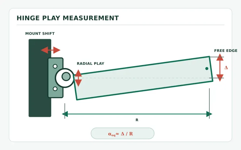
Wear marks matter because damaged dimensions must not become the new specification. Determining why the interface wore, whether only the pin should be replaced, and what repair is acceptable is a different task; the separate industrial hinge play diagnosis follows that failure path in detail.
| Observed Feature | How the Reading Can Mislead | Better Replacement Evidence |
|---|---|---|
| Flat or stepped pin | The smallest diameter includes material loss | Measure multiple clock positions and unworn axial zones; compare with a drawing or retained part |
| Oval knuckle bore | One diameter cannot describe the original round bore | Record loaded and cross-load directions at both ends |
| Elongated mounting hole | The current opening is not the released hole size or center | Use unworn boundaries, companion holes, witness marks, and receiving-structure coordinates |
| Compressed thrust washer | Current thickness includes service loss or deformation | Record washer material and geometry; compare with an unused sample or assembly stack requirement |
| Bent leaf | Flattening it erases the installed offset and residual distortion | Measure as found, then document the intended mounting planes separately |
| Paint ridge or corrosion scale | Caliper jaws read buildup rather than base geometry | Record finish condition and clean only a controlled measurement area |
Several used hinges from the same assembly can help, but they are not automatically replicas. Upper and lower hinges may carry different loads and may have been shimmed differently. Keep their records separate, then compare corresponding features. Agreement across unworn areas is more useful than averaging all readings into one clean-looking number.
Handing and Retention Features
A simple butt hinge can look reversible on a white background. The installed part may not be. Mark top and bottom, opening direction, door leaf, and frame leaf before deciding that a candidate can be flipped.
- Countersinks or counterbores may exist on only one side.
- The pin head, clip, peened end, or removal direction may depend on gravity and service access.
- Unequal leaves, offset bends, weld lands, or stops can assign one leaf to the frame.
- A knuckle sequence may expose a different end face when the hinge is inverted.
- A washer, shoulder, or axial bearing feature may carry load in only one orientation.
- Drainage, seal overlap, or tamper resistance may prevent an otherwise possible reversal.
Photograph both faces and both pin ends. A single front view can hide the one feature that makes the replacement handed.
Measurement Tools and Confidence
Use a tool that can resolve the feature being judged, and record the tool with the result. More decimal places do not repair poor access, worn contact surfaces, jaw misalignment, or an undefined datum.
| Tool | Useful For | Important Limitation |
|---|---|---|
| Steel rule or tape | Overall envelope and installation context | Not suitable for pin fits, hole size, or small offsets |
| Digital or dial caliper | Leaf width, open width, hole diameter, slot size, and accessible offsets | Jaw position and contact angle can hide ovality or produce false centers |
| Outside micrometer | Pin diameter and leaf thickness at controlled points | Measures only the contacted direction and location |
| Pin or plug gages | Screening accessible round bores | Entry does not prove straightness, full-length size, or coaxiality |
| Surface plate and height gage | Repeatable hole and edge coordinates from a mounting face | The selected face must be stable and representative |
| CMM or optical system | Complex offsets, coordinate patterns, and controlled reverse measurement | Still requires correct datums, feature definitions, and wear interpretation |
| Angle gage or digital inclinometer | Formed leaf angle and stop relationship | Loose leaves and curved surfaces need a defined seating method |
Instrument resolution is not the same as measurement uncertainty or part tolerance. Do not derive a manufacturing tolerance from one used hinge. If several measurements vary, preserve the individual readings and state the locations. The engineering team can then decide whether the variation represents wear, form, measurement method, or actual product variation.
A Replacement Record That Can Be Quoted
The supplier does not need a polished reverse-engineered drawing to begin screening. A disciplined measurement sheet, annotated photographs, and the door context are usually more useful than an unlabeled CAD outline.
In HTAN replacement reviews, another front photograph rarely resolves the last uncertainty. A closed side view with the mounting faces and pin centerline marked is usually more useful. It exposes the axis offset, leaf stack, spacers, and frame return that disappear in a straight-on product image.
| Record Group | Minimum Content | Why It Matters |
|---|---|---|
| Identity | Equipment, hinge station, quantity, top/bottom, door/frame leaf | Prevents mixed parts and reversed orientation |
| Installed condition | Door gap, opening direction, required angle, shims, nearby obstructions | Preserves the assembly relationship |
| Leaf geometry | Height, open width, individual leaf widths, thickness, edge form | Defines the mounting envelope |
| Hole pattern | Hole type, size, X/Y center coordinates, slot direction, countersink side | Controls attachment and axis location |
| Pivot geometry | Pin, knuckle, segment order, gaps, projections, washers, bushings | Identifies the rotating interface and service features |
| Closed geometry | Closed thickness, axis-to-face offsets, steps, designed leaf gap | Controls door position and sweep |
| Condition notes | Wear, corrosion, bending, elongated holes, missing parts, cleaned areas | Separates observed damage from likely nominal geometry |
| Measurement basis | References, tools, units, reading locations, repeated values | Makes the numbers interpretable |
| Application context | Door size and mass if known, environment, cycles, vibration, removal need | Prevents a geometric match from being treated as complete approval |
Include at least four clear views: the hinge installed with surrounding structure, the complete hinge open, a closed side view showing mounting-face offsets, and an end view showing the pin and knuckle arrangement. Add a ruler or scale in the same plane as the feature, but do not rely on perspective photographs for final dimensions.
If the measurements will become a controlled engineering drawing, ASME Y14.5 provides rules for stating and interpreting dimensions and geometric tolerances. It does not recover the original tolerance from a worn sample, define the acceptable replacement fit, or approve the installed door. Those requirements still need engineering ownership.
Compare the Candidate in the Assembly
Once a candidate is identified, compare it in the same order used for measurement. Begin with architecture and handing. Then compare the axis-to-hole pattern, closed thickness, mounting faces, pin retention, and opening envelope. Only after the geometry is credible should material, finish, load evidence, and service life be approved.
A candidate from the heavy-duty hinge range may provide a useful starting point when the old part supported a large or frequently operated door. The category name is not proof of interchangeability. The replacement still has to match the installed load path, fastening structure, axis location, and required evidence.
Use a sample on the real door or a representative fixture. Check that every leaf seats without being pulled into position, all hinge pins share the intended axis, the door reaches the required angle, and the latch and gasket return to their working positions. Operate the door through the full range before applying a finish judgment from the closed position alone.
- No new interference at the frame return, trim, seal, fasteners, or pin ends
- No forced leaf seating or visible panel distortion during tightening
- Door gap and latch engagement remain within the assembly requirement
- Pin retention and removal direction match the service plan
- Fasteners, inserts, or weld lands are compatible with the receiving structure
- Required load or cycle evidence refers to a relevant mounting and test condition
A bench match shows that two parts look and measure alike. An installed check shows whether the replacement preserves the door.
Send the Measurement Record with the Photos
Send the marked installed views, open and closed hinge dimensions, hole coordinates, pin and knuckle details, finish condition, and the door application. HTAN can compare the record with available hinge models and identify which features still require a sample or assembly check.
Butt Hinge Replacement Measurement FAQ
How do I measure a butt hinge for replacement?
Record the installed orientation first. After removal, measure overall height, open width, each leaf width and thickness, the hole pattern from the pin axis and one end, pin and knuckle geometry, closed thickness, pivot offset, retention features, and any wear that may have changed the original dimensions.
Should a butt hinge be measured installed or removed?
Both conditions provide different information. Installed measurements preserve the door gap, orientation, shim stack, fastener position, and surrounding clearance. Removed-part measurements provide access to the leaves, holes, pin, knuckles, and closed geometry. Record the installed condition before loosening the hinge.
Which butt hinge dimension is most important for replacement?
No single dimension proves interchangeability. Overall size screens candidates, while the pin-axis location, axis-to-hole coordinates, closed thickness, mounting-face offsets, hole form, and opening envelope determine whether the door returns to the same position.
Can I use a digital caliper to measure a hinge pin?
A caliper can provide an initial pin measurement. A micrometer is better for detecting small diameter differences. Measure at several axial positions and rotational directions because a worn pin may have flats or steps that one reading misses.
Can I identify a replacement hinge from photos alone?
Photos can identify the hinge family, orientation, leaf shape, pin ends, and visible mounting features. They cannot reliably establish hole coordinates, leaf thickness, pin diameter, closed offset, or wear. Use annotated photographs together with measured dimensions and the installed door context.
How do I account for wear when measuring an old hinge?
Keep observed dimensions separate from likely nominal dimensions. Measure pins and bores in multiple directions and locations, retain wear marks, and compare unworn areas with an original drawing, unused sample, companion hinge, or supplier data. Do not average damaged and unworn readings into one assumed size.
Are two butt hinges interchangeable if their height and width match?
Not necessarily. They may differ in pin-axis offset, closed thickness, individual leaf width, hole coordinates, countersink side, knuckle stack, pin retention, handing, material, or load evidence. A candidate should be checked in the actual door assembly.
What photos should I send for an industrial butt hinge replacement?
Send the complete door and frame, every hinge station, both faces of the hinge, both pin ends, the hinge open, a closed side view, the mounting holes, and any shims, washers, bushings, damage, or interference. Include a scale in the same plane as the photographed feature.


 English
  한국어
한국어  Русский
  Español
  Italiano
  Deutsch
  Français
  Português