

How to Calculate an Industrial Door’s Center of Gravity From the Hinge Axis
The center of gravity of an industrial door belongs to the complete moving assembly, not simply to the rectangular outline of the door sheet. The panel, formed returns, stiffeners, window, HMI, latch, handle, insulation, wiring and guards can all change where the finished door mass acts.
For an engineering review, measure that position from the actual installed hinge pin centerline. A distance taken from the panel edge, leaf edge or mounting-hole row may look precise while using the wrong datum. Two doors with the same width and total mass can therefore place very different demands on the hinge line.
Quick answer: list every component that moves with the door, record each component mass mi and its center position xi from the installed hinge axis, then calculate:
xCG = Σ(mixi) / Σmi
Use the finished door configuration represented by the released drawing and bill of materials. For a door-sized assembly in Earth’s nearly uniform gravitational field, the center of mass and center of gravity can be treated as the same location.
When HTAN reviews an industrial butt hinge application, we treat a CG value as usable only when it is tied to a named door configuration and a visible hinge-axis datum. The calculation locates the door mass. Hinge reactions, mounting strength and allowable capacity remain later engineering checks.
Establish the Hinge Axis and Coordinate Directions
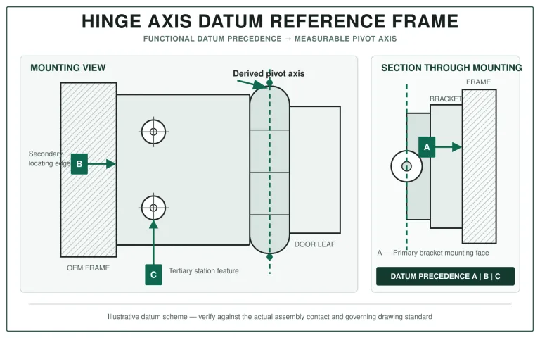
Use the installed pivot axis as datum zero. For a conventional butt hinge, this is the line through the centers of the hinge pins in the assembled position. An offset barrel, spacer, recessed leaf or formed mounting bracket can place that line away from the visible door edge.
Define the positive coordinate directions on the door layout before entering any component positions. A practical convention for a vertical side-opening door is:
| Coordinate | Suggested Direction | What It Describes |
|---|---|---|
| x | From the hinge axis toward the latch edge | The primary lever arm used in the gravity-induced sagging load case |
| z | Upward along the door height | Whether equipment mass sits above or below the hinge layout |
| y | Out of the nominal door plane | Mass created by deep housings, projecting displays, handles or guards |
Every distance in the calculation must use the same origin and sign convention. The door edge, leaf edge, barrel outside diameter and mounting-hole centerline are useful manufacturing dimensions, but none automatically represents the rotational axis.
For a multi-hinge door, the installed pins should form one compatible axis. A CG coordinate can still be calculated when the hinges are misaligned, but it cannot describe the binding and preload caused by incompatible pivot centerlines. Resolve the intended axis on the assembly drawing before using the result in a hinge review.
When Half the Door Width Is a Valid Estimate
Half the door width is a useful first estimate for a uniform rectangular panel whose reference edge lies on the hinge axis. Once the axis is offset or the moving assembly becomes asymmetric, the finished-door CG must be calculated from its components.
Let B be the panel width and p the signed distance from the hinge axis to the panel reference edge, positive toward the latch. The horizontal center of a uniform rectangular panel is:
xpanel = p + B / 2
This result describes the bare panel. A display near the latch moves the assembled CG outward, while a hinge-side reinforcement can pull it back. A window changes the calculation twice: panel material is removed, then glazing, a frame and fasteners are added at their own positions.
Define the Complete Moving Assembly
Draw a boundary around everything that travels with the door when it opens. Count each item once. Hardware fixed to the frame stays outside the moving-mass model even when it is supplied as part of the same latch or hinge set.
| Item | Include in Moving Mass? | How to Treat It |
|---|---|---|
| Door skin and formed returns | Yes | Use the fabricated geometry or the measured finished-panel mass. |
| Door-side hinge leaf | When its contribution is material | Include the moving hinge components and document any approximation. |
| Frame-side hinge leaf and latch keeper | No | They remain on the stationary structure. |
| Stiffeners, insulation and bonded liners | Yes | Use their installed masses and component centers. |
| Window, HMI, latch, handle and guard | Yes | Keep concentrated hardware separate because its position strongly affects the result. |
| Door-mounted cable, hose or grounding strap | Moving portion only | Include the portion carried by the door without counting the stationary harness. |
| Gasket fixed to the frame | No | It can change closing force but does not move with the door. |
| Optional accessory | Configuration-dependent | Calculate each released configuration or identify the governing arrangement. |
A bare-door weight often excludes the parts that matter most to the lever arm: lock rods, glazing, a document pocket, an operator display or a cable bundle near the latch side. Conversely, using the mass of a complete latch set can overstate the moving mass when the keeper and part of the linkage remain on the frame.
Build a Mass-and-Position Table
Break the assembly into components whose mass and local center can be supported by a released drawing, CAD mass property, supplier value or physical weighing. Large uniform parts can remain single rows. Concentrated hardware should stay separate because the same mass produces a different result when it moves closer to or farther from the hinge axis.
| Component | Mass, mi | xi From Hinge Axis | zi From Vertical Datum | Evidence |
|---|---|---|---|---|
| Fabricated door panel | Measured or calculated | Panel CG | Panel CG | Released CAD, drawing or scale |
| Stiffener assembly | Subassembly mass | Assembly CG | Assembly CG | CAD or weighed subassembly |
| Window or HMI | Installed mass | Component mass center | Component mass center | Supplier data or scale |
| Latch and handle | Door-side hardware only | Hardware CG | Hardware CG | Part model or weighed set |
| Removed cutout | Negative mass | Cutout centroid | Cutout centroid | Material and cut geometry |
Keep one unit system throughout the table. Kilograms and millimeters are convenient for locating the CG; pounds-mass and inches can also be used. Each coordinate must describe that component’s own center of gravity rather than its mounting hole, outside edge or geometric center unless those points genuinely coincide.
Check the CAD Model Before Accepting Its CG
A CAD center-of-mass marker is only as reliable as the assembly behind it. Review the material assignment and inclusion state of every part that can change the result. Imported supplier geometry may carry a default density. Reference envelopes may have been modeled as solid bodies. Fasteners can appear in the graphics while remaining excluded from the mass calculation.
Confirm the active configuration as well. A suppressed liner, glazing panel, guard or lock rod can leave the exterior view looking complete while changing the mass properties. A simplified HMI may have the correct outside dimensions and the wrong mass. A mirrored door assembly may also retain hardware in the original position if the configuration was copied without rebuilding the mass model.
Export three values together: total moving mass, CG coordinates and the named assembly configuration. Compare the CAD mass with the BOM roll-up before accepting the coordinates. A difference between them usually points to a missing component, duplicated body, wrong density or mismatched revision.
Calculate the Horizontal CG Offset
For discrete components, first sum the moving mass:
mT = Σmi
Then calculate the horizontal center of gravity from the installed hinge axis:
xCG = Σ(mixi) / Σmi
The equation is a mass-weighted average. NASA Glenn’s center-of-gravity explanation describes the same general principle for distributed and segmented mass. The industrial-door work lies in defining the correct moving components and measuring every position from the real pivot axis.
Because every component experiences essentially the same gravitational acceleration, mass values can be used directly in the ratio; g cancels. The intermediate value in kg·mm or lb·in is a mass moment used to locate the CG. It is different from the force moment later applied to the door support system.
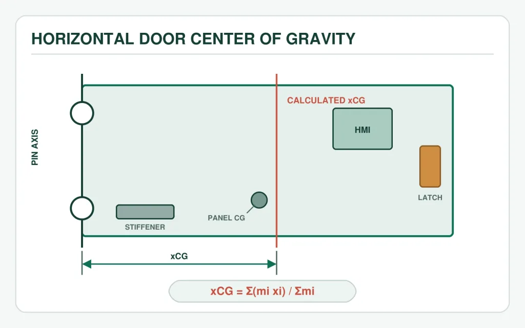
Worked Example: An 840 mm Door With an Outboard HMI
The simplified 840 mm door below makes each calculation step easy to check by hand.
| Component | Mass | x From Hinge Axis | m × x |
|---|---|---|---|
| Uniform formed panel | 18.0 kg | 420 mm | 7,560 kg·mm |
| HMI and window assembly | 5.0 kg | 680 mm | 3,400 kg·mm |
| Latch and handle | 1.0 kg | 780 mm | 780 kg·mm |
| Hinge-side stiffener | 2.0 kg | 120 mm | 240 kg·mm |
| Total | 26.0 kg | — | 11,980 kg·mm |
The assembled horizontal CG is 11,980 / 26.0 = 460.8 mm, rounded to 461 mm from the hinge axis. Half the door width would place it at 420 mm. The HMI and latch shift the finished-door lever arm outward by approximately 41 mm even though the overall door width has not changed.
Update the CG When Hardware Changes
If the current door has total mass mT at xCG, and a new component has mass ma at xa, the revised coordinate is:
xCG,new = (mTxCG + maxa) / (mT + ma)
Adding a 1.5 kg accessory at 760 mm to the example above moves the CG from 460.8 mm to approximately 477.1 mm. The added part is less than six percent of the original door mass, yet its outboard position shifts the lever arm by more than 16 mm.
The same calculation can compare two proposed mounting positions before the drawing changes. Once the location is released, update the controlled mass table so the recorded CG continues to match the production door.
Account for Cutouts and Unreleased Components
Treat Removed Material as Negative Mass
If the panel row represents a complete uncut sheet, enter removed material as a negative component at the cutout centroid. Then add the installed window, display, fan or access assembly at its own mass center.
For a uniform cutout of mass mr centered at xr, use -mr and -mrxr in the mass and mass-moment sums. This approach also works for a machined opening, trimmed corner or relocated pocket.
When the panel mass comes from the finished CAD body or from post-fabrication weighing, the cutout has already been removed. Label the evidence as blank panel, fabricated panel or finished panel so the subtraction is not applied twice.
Use a Range for an Unreleased Accessory
An early design may contain a display, lock or cable package whose final mass and position are still changing. Report a CG range instead of hiding that uncertainty inside one over-precise value. Evaluate the lightest and heaviest credible versions at their permitted locations, keeping each combination physically possible.
If both bounds lead to the same hinge architecture, the project can continue while the component is finalized. When the range crosses a hinge or mounting decision threshold, weigh the candidate component or freeze its installation zone before releasing the hardware selection.
Calculate Vertical and Out-of-Plane Coordinates When Needed
The horizontal coordinate xCG is the main input for the gravity-induced sagging moment of a vertical side-opening door. The same mass table can retain vertical and out-of-plane coordinates:
zCG = Σ(mizi) / Σmi
yCG = Σ(miyi) / Σmi
The vertical coordinate shows whether equipment mass is concentrated above or below the hinge layout. The out-of-plane coordinate becomes relevant when a deep enclosure, projecting display, handle or guard places mass away from the nominal door plane. Keep the three coordinates separate because each direction enters the structural model differently.
Side-opening door versus horizontal lid: gravity creates a structural bending demand at the hinge line of a vertical side-opening door. It does not create holding torque around the vertical hinge axis in the same way that gravity acts around the horizontal axis of a top-opening lid.
Verify the Calculated CG on the Physical Door
A physical check is valuable when the CAD model contains simplified supplier parts, mixed materials or configuration uncertainty. The measurement setup must carry the door through known support points without allowing a cable, hose, fixture or operator to take part of the load.
- Route flexible connections so they neither lift nor pull the assembly during the reading.
- Tare trays, blocks, slings and scale adapters before loading the door.
- Keep the intended support points at the same elevation unless the calculation includes their geometry.
- Remove transport blocks and temporary handling parts that are absent from the released door.
- Record the scale identification, resolution and door configuration with the result.
Two-Support Reaction Method
A manageable uninstalled door can be placed horizontally on two vertical reaction points with known positions. Put support A near the hinge side and support B near the latch side. Let their coordinates be xA and xB, with spacing L = xB – xA. After taring the fixtures, record reactions RA and RB.
The CG coordinate along the support line is:
xCG = xA + [RB × L / (RA + RB)]
If the scales display mass-equivalent readings rather than force, the same ratio applies because gravitational acceleration cancels. The sum of the two readings should also agree with an independent measurement of the same completed door within the project’s measurement tolerance.
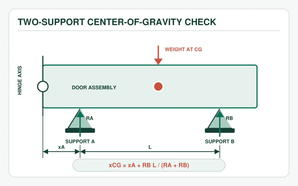
- Support the door with a fixture suitable for its complete mass and prevent sliding without adding another vertical reaction.
- Measure both support coordinates from the hinge-axis datum used in the calculation.
- Tare the fixtures and record scale identification and resolution.
- Allow both readings to stabilize with no contact from hands, cables or hoses.
- Calculate the CG coordinate and compare it with the component mass roll-up.
Balance and Suspension Checks
For a small assembly that can be handled safely, a narrow support edge can locate the balance line. Move the door slowly until it remains level without restraint, then measure the line from the same hinge-axis datum. Friction, a broad support surface or operator contact can make the result less sensitive.
Suspension provides another check for an irregular lightweight door. Hang the assembly from one approved point and mark the vertical plumb line through that point. Repeat from a second point; the intersection identifies the CG projection. Large fabricated doors are better handled with a controlled reaction fixture or a verified component mass model.
Handling a heavy door safely: use lifting equipment and fixtures rated for the complete assembly. Keep the installed door supported whenever a load-carrying hinge, bracket or fastener is loosened.
Reconcile Calculated and Measured Mass
Compare the summed component mass with the measured mass of the same completed configuration. A mismatch can reveal a missing cable set, duplicated hardware, incorrect material density, cutout counted twice, untared fixture or option installed in only one source.
Set the acceptable difference from the project requirement, scale capability, mass-model fidelity and sensitivity of the downstream hinge review. A small enclosure door and a welded vehicle compartment door may require different equipment and uncertainty limits.
Keep the door drawing revision, BOM revision, CAD configuration, calculation date and physical-check state together. A change to glazing, lock rods, reinforcement, insulation or cable routing creates a new mass configuration and requires the CG record to be reviewed again.
Record the Result on the Door Layout
Place the CG result beside a door view that shows the coordinate origin, positive directions, pivot axis and component arrangement. The drawing should let another engineer reconstruct what the number means without guessing which edge or hardware state was used.
| Field | What to Record | Why It Matters |
|---|---|---|
| Door configuration | Drawing, BOM and CAD configuration revision | Prevents an old CG value from following a changed assembly. |
| Moving mass | Total mass, units and evidence basis | Separates calculated, supplier and measured inputs. |
| Axis definition | Installed pin centerline and positive directions | Removes ambiguity from every component coordinate. |
| Horizontal CG | xCG from the hinge axis | Provides the lever arm for the vertical side-door load case. |
| Other coordinates | yCG and zCG where relevant | Preserves the complete mass distribution for later analysis. |
| Verification | CAD, mass roll-up, reaction check or another controlled method | Shows how the value was obtained and physically checked. |
| Operating state | Installed accessories, cables, fluids and removable items | Defines the door condition represented by the result. |
Use the CG Result in the Hinge Load Review
The verified mass and CG locate the gravitational load; they do not determine how two, three or four hinges share the resulting reactions. Support spacing, axis alignment, leaf and pin construction, fasteners or welds, reinforcement, door stiffness and frame compliance still shape the installed load path.
Carry the mass and CG record into the separate review of hinge spacing and load distribution for long industrial doors. Once the support layout is established, evaluate the mounting interfaces, environment, duty cycle, stops and butt hinge leaf thickness. The finished assembly and the supplier’s stated rating basis remain the final references for model approval.
Send HTAN the Door Mass Layout
For a model review, send the door drawing and revision, complete moving mass, component mass table, hinge-axis definition, CG coordinates, proposed hinge quantity and positions, mounting sections and any physical verification record. HTAN can compare that package with relevant heavy-duty hinge options and identify any missing interface data before samples are selected.
Industrial Door Center of Gravity FAQ
How do you calculate the center of gravity of an industrial door?
List every component that moves with the door, record each mass and its center position from the installed hinge axis, then calculate xCG = Σ(mi xi) / Σmi. Use the finished door configuration, including door-mounted hardware, windows, insulation, wiring and guards.
Is an industrial door’s center of gravity always at half its width?
Only a uniform rectangular panel has its own center at half its width. An offset hinge axis, window, HMI, handle, latch, stiffener, insulation, cutout or cable assembly can move the finished-door CG away from that position.
Where should the CG distance be measured from for butt hinge selection?
Measure from the actual installed hinge pin centerline or common pivot axis. A panel edge, leaf edge, barrel outside diameter or mounting-hole row should be used only when the drawing clearly converts that reference to the pivot axis.
Should the hinge mass be included in the door center of gravity?
Include the door-side leaf and other hinge components that move with the door when their contribution is material to the required accuracy. Exclude the stationary frame-side leaf. Record the basis of any approximation when only complete-hinge mass is available.
How should a window cutout be included in the CG calculation?
When the panel row represents an uncut blank, subtract the removed panel material as negative mass at the cutout centroid, then add the installed window, frame and door-side fasteners at their own mass centers. Skip the subtraction when the panel mass already represents the fabricated part.
What should I do when an accessory mass is not finalized?
Calculate a CG range using the lightest and heaviest credible accessory versions at their permitted positions. If that range crosses a hinge or mounting decision threshold, weigh the candidate part or freeze its installation zone before releasing the hinge selection.
How can an industrial door center of gravity be verified physically?
For a safely supported uninstalled door, use two known vertical reaction points and calculate the CG from their readings. A controlled balance or suspension method can also be used for a smaller assembly. Tare the fixtures and keep cables, hoses, hands and other contacts from carrying part of the load.

 English
  한국어
한국어  Русский
  Español
  Italiano
  Deutsch
  Français
  Português